How to Recognize and Draw AC and DC Symbols
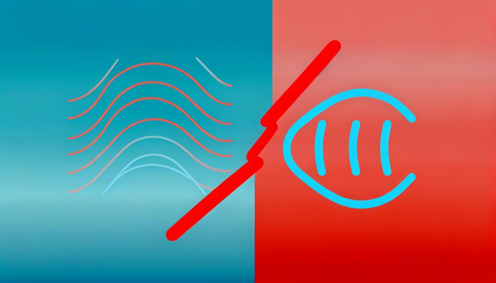
The symbol for alternating current (AC) is represented by a sine wave, illustrating the oscillating nature of voltage or current, with amplitude indicating peak voltage and wavelength reflecting frequency. In contrast, direct current (DC) is symbolized by a straight line accompanying a dashed line, denoting a constant, unidirectional flow of electricity.
These standardized symbols, established with the help of the International Electrotechnical Commission (IEC), ensure clear communication in circuit diagrams and power supply labels. Understanding these symbols is essential for interpreting electrical systems and enhancing safety and efficiency.
Explore further to understand their applications and significance in detail.
Key Takeaways
- The AC symbol is a sine wave representing alternating current's oscillation.
- The DC symbol features a straight line with a dashed line indicating unidirectional flow.
- AC symbols are crucial for understanding voltage amplitude and frequency.
- DC symbols highlight constant current flow and polarity.
- Standardized symbols aid in clear communication and safety in electrical engineering.
AC Symbol Overview
The symbol for alternating current (AC) is typically represented by a sine wave, reflecting the periodic oscillation of voltage or current direction over time. This sine wave symbolizes the cyclical nature of AC, where the current alternates between positive and negative values.
The amplitude represents the peak voltage, while the wavelength corresponds to the frequency, usually measured in Hertz (Hz). The sinusoidal waveform is advantageous for efficient transmission over long distances due to reduced energy losses.
Additionally, the phase angle in polyphase systems, such as three-phase power, is vital for analyzing power distribution and load balancing. Understanding the sine wave symbol is essential for comprehending various applications, from household power supply to industrial machinery and complex electronic circuits.
DC Symbol Basics
Representing direct current (DC), the symbol typically features a straight line with a dashed line underneath, indicating a unidirectional flow of electric charge. This graphical representation is essential for distinguishing DC from alternating current (AC) in schematics and diagrams. Understanding the DC symbol involves recognizing its components and applications:
- Straight Line: Represents the constant, unidirectional nature of the current flow in DC systems.
- Dashed Line: Illustrates the potential difference and directionality, emphasizing the non-alternating nature of DC.
- Polarity Notation: Often includes positive (+) and negative (-) signs to denote the direction of current flow.
- Usage in Diagrams: Commonly used in circuit diagrams to indicate power sources, batteries, and other DC components.
These elements guarantee clear and precise communication in electrical documentation and design.
Historical Context
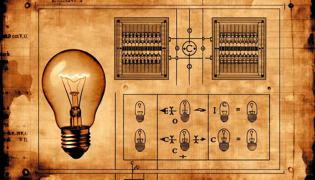
Understanding the evolution of electrical symbols, particularly for AC and DC, requires examining their historical origins and the development of electrical engineering standards. Initially, electrical symbols were not standardized, leading to notable inconsistencies and confusion.
The unification process began in the late 19th and early 20th centuries, driven by the growing need for a coherent understanding of electrical systems. The International Electrotechnical Commission (IEC), founded in 1906, played a pivotal role in standardizing these symbols.
The DC symbol, a straight line with three dashes, and the AC symbol, a sine wave, emerged from these efforts. These standardized symbols facilitated clear communication and documentation, advancing the field of electrical engineering and ensuring global consistency in electrical diagrams and literature.
Circuit Diagram Use
In circuit diagrams, the standardized symbols for AC and DC play an essential role in accurately representing and differentiating between alternating current and direct current components within electrical systems. These symbols guarantee clarity and uniformity in design and troubleshooting.
The AC symbol typically consists of a sine wave, while the DC symbol is represented by a straight line with dashed lines underneath it.
Key uses in circuit diagrams include:
- Identifying Power Sources: Clearly marks whether the power supply is AC or DC.
- Component Specification: Distinguishes components designed for specific current types.
- Circuit Behavior Analysis: Facilitates understanding of how the circuit will operate under different current types.
- Safety and Compliance: Guarantees adherence to industry standards and safety regulations.
These conventions are critical for precise communication among engineers and technicians.
Power Supply Labels
Power supply labels provide critical information regarding voltage specifications, guaranteeing proper and safe usage of electrical devices. These labels adhere to stringent international standards, which dictate the format and symbols used to convey whether the supply is AC or DC.
Understanding these indicators and standards is essential for both electrical engineers and end-users to prevent equipment damage and guarantee compliance with safety regulations.
Voltage Indicators Decoded
Decoding the various voltage indicators on power supply labels necessitates an understanding of standardized symbols and their specific meanings. Accurate interpretation guarantees proper usage and safety.
Key voltage indicators on power supply labels include:
- AC Voltage (AC): Represented by a tilde (~), indicating alternating current voltage. Essential for devices operating on fluctuating voltages.
- DC Voltage (DC): Denoted by a solid line above a dashed line (⎓), signifying direct current voltage. Essential for electronics needing constant voltage.
- Voltage Range: Shown as a range (e.g., 100-240V), specifying the acceptable input voltage range, ensuring compatibility with various power sources.
- Polarity Symbols: Plus (+) and minus (−) signs, indicating the correct connection orientation, crucial for preventing damage to the device.
Understanding these symbols helps guarantee safe and efficient operation of electrical devices.
Labeling Standards Explained
Building on the knowledge of voltage indicators, it is important to comprehend the labeling standards that govern power supply labels to guarantee proper identification and usage.
Power supply labels must adhere to international standards such as IEC 60950 and IEEE standards, which ensure consistent and accurate information. Key components include voltage ratings, current ratings, frequency, and polarity.
Symbols for AC (alternating current) and DC (direct current) are standardized, with a tilde (~) representing AC and a solid line with a dashed line underneath (⍓) indicating DC.
Additionally, labels often include safety certifications like UL, CE, and FCC marks, which indicate compliance with safety and electromagnetic compatibility regulations. Understanding these labels is essential for safe and efficient device operation.
Safety Significance
Understanding the safety importance of AC and DC symbols is essential for electrical hazard awareness. It allows operators to recognize and mitigate potential risks associated with various power supplies.
Proper labeling practices guarantee that all equipment and power sources are clearly marked, facilitating safe usage and maintenance procedures. These measures are fundamental in preventing electrical accidents, safeguarding both personnel and infrastructure.
Electrical Hazard Awareness
Recognizing the symbols for AC (Alternating Current) and DC (Direct Current) is crucial for electrical hazard awareness. These symbols help identify the type of electrical current present and inform the necessary safety precautions. Each type of current presents unique risks and requires specific safety measures.
For instance, AC is often found in household wiring, while DC is common in battery-operated devices.
Electrical hazard awareness entails:
- Identifying Current Type: Determine if the system uses AC or DC.
- Understanding Risks: AC can cause severe muscle contractions; DC can lead to electrical burns.
- Wearing Appropriate PPE: Use insulating gloves and eye protection.
- Implementing Lockout/Tagout Procedures: Ensure circuits are de-energized before maintenance.
Adhering to these guidelines can greatly reduce electrical hazards.
Proper Labeling Practices
Proper marking practices, vital for guaranteeing electrical safety, involve clearly labeling equipment and circuits with precise and easily recognizable symbols to indicate the type of current and associated hazards. These practices not only improve operational efficiency but also reduce risks of electrical accidents. Labels must include standardized symbols for Alternating Current (AC) and Direct Current (DC) along with voltage ratings and hazard warnings. Proper marking guarantees that technicians and engineers can quickly identify the nature of electrical systems, thereby facilitating safe maintenance and troubleshooting activities.
| Symbol | Description |
|---|---|
| AC | Alternating Current |
| DC | Direct Current |
| ⚠️ | Electrical Hazard |
Accurate marking is essential for preventing misidentification and ensuring compliance with safety regulations.
Preventing Electrical Accidents
Implementing standardized labeling practices is a fundamental step in preventing electrical accidents, as clear identification of AC and DC systems guarantees that personnel can adhere to appropriate safety protocols during maintenance and operations. This approach mitigates risks by providing unambiguous information about the electrical environment, thus fostering a safer workplace.
Adherence to these practices involves several critical actions:
- Color Coding: Use specific colors to differentiate between AC and DC circuits, reducing the likelihood of errors.
- Warning Signs: Place prominent warning signs to alert technicians of high-voltage areas.
- Periodic Inspections: Conduct regular inspections to make sure labels remain visible and accurate.
- Training Programs: Implement detailed training programs on the significance of labeling and associated safety measures.
These measures are essential for maintaining operational safety and preventing electrical hazards.
Applications in Devices
In the world of electronic devices, the utilization of alternating current (AC) and direct current (DC) is essential to the operation and functionality of various systems.
AC is prevalently used in household and industrial settings for powering electric motors, lighting, and heating systems due to its efficiency in transmitting power over long distances.
Conversely, DC is integral in applications requiring stable and precise voltage, such as in battery-operated devices, electronic circuits, and computing systems.
Devices like smartphones, laptops, and electric vehicles rely on DC for their operation, often necessitating AC-to-DC conversion through rectifiers.
Understanding the specific roles of AC and DC in these applications is vital for optimizing device performance and ensuring electrical compatibility.
Troubleshooting Tips
When diagnosing issues in electronic devices that utilize both AC and DC power, it is essential to systematically check for common problems such as faulty connections, component failures, and incorrect voltage levels.
Follow these steps to perform accurate troubleshooting:
- Inspect connections: Verify all AC and DC connections are secure and free from corrosion or wear.
- Test components: Use a multimeter to check the functionality of capacitors, resistors, and other components.
- Measure voltage: Ensure voltage levels align with the device specifications by measuring at various points within the circuit.
- Check for shorts: Look for potential short circuits that could result in malfunction or damage.
Conclusion
In the world of electrical currents, AC and DC symbols serve as the guiding stars leading engineers through the complex circuitry landscape.
These symbols, steeped in historical importance and practical usefulness, are essential for the design, labeling, and safe operation of electrical devices.
Much like ancient cartographers who charted unexplored territories, these symbols map the flow of electricity, ensuring accuracy, safety, and functionality in modern technological applications.
Understanding these symbols is crucial for efficiently moving through the electrical world.