Identifying the Symbol for a Pressure Relief Valve
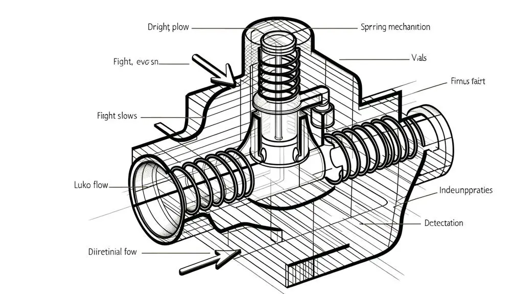
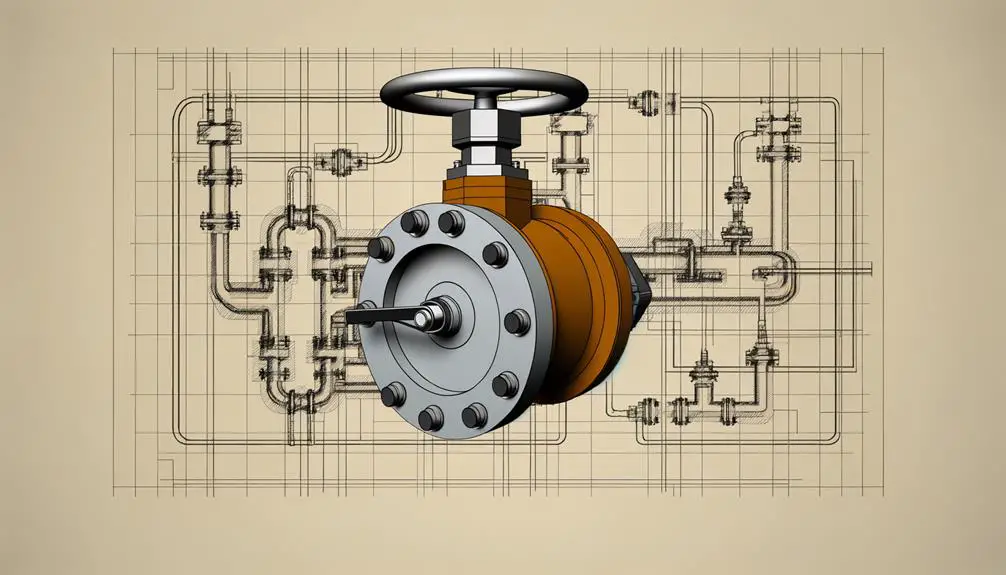
The symbol for a pressure relief valve is a standardized graphical depiction used within engineering schematics to denote a safety device designed to release excess pressure. This symbol typically includes elements such as geometric shapes and lines illustrating the valve body, inlet/outlet ports, and spring mechanism.
Adherence to industry standards like ISO and ANSI guarantees uniformity and minimizes risks of misinterpretation. Variations may occur to fit specific industry practices or regional guidelines, securing clarity and safety.
These representations are vital for system analysis, design accuracy, and safety compliance, ultimately contributing to the overall reliability and efficiency of engineering systems.
Key Takeaways
- Standardized symbols for pressure relief valves include geometric shapes like rectangles with arrows indicating flow direction.
- Symbols often feature a spring mechanism representation to denote the valve's pressure regulation function.
- Variations in symbols exist due to differing industry standards, such as ISO and ANSI.
- Symbols may include additional annotations indicating set pressure values and operational states.
- Accurate interpretation of these symbols is crucial for ensuring system safety and efficiency.
Importance of Symbols
In the field of engineering and technical design, the use of standardized symbols, such as those representing pressure relief valves, is vital for ensuring clear and unambiguous communication among professionals. These symbols facilitate the accurate interpretation of schematics and technical documents, which is essential for the design, maintenance, and operation of complex systems.
Utilizing standardized symbols mitigates the risk of misinterpretation, thereby enhancing safety and efficiency. Moreover, these symbols provide a universal language that transcends linguistic and geographical barriers, promoting a cohesive understanding in multinational projects.
Effective use of pressure relief valve symbols ensures compliance with industry standards and regulatory requirements, contributing to the overall reliability and safety of engineering systems.
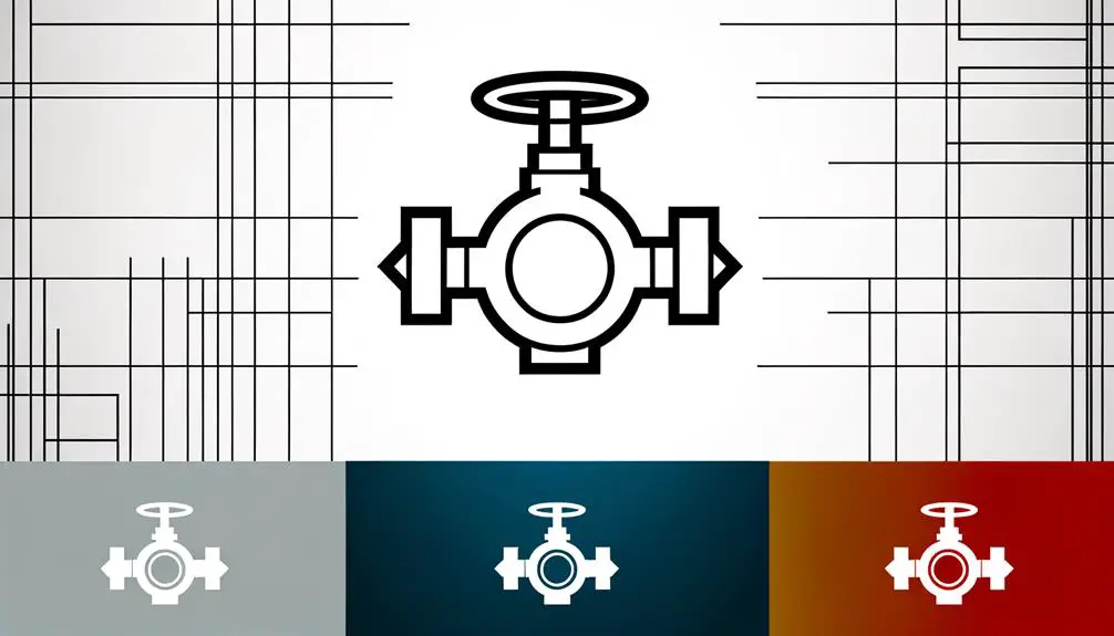
Basic Symbol Design
Standardized pressure relief valve symbols are meticulously designed to convey specific technical information, ensuring that engineers and technicians can quickly and accurately interpret them within complex schematics. These symbols typically include geometric shapes and lines that represent the functional aspects of the valve, such as flow direction and relief settings. The clarity and precision of these symbols are pivotal for avoiding misinterpretations in system designs and maintenance procedures.
| Component | Symbol Element | Description |
|---|---|---|
| Valve Body | Rectangle | Main structure of the valve |
| Inlet/Outlet Ports | Arrows | Direction of fluid flow |
| Spring Mechanism | Zigzag line | Indicates adjustable set point |
| Relief Setting | Arrow with a line | Represents pressure adjustment |
| Discharge Path | Broken line | Shows fluid exit route |
Accurate symbol representation is essential for ensuring system reliability and safety.
Common Variations
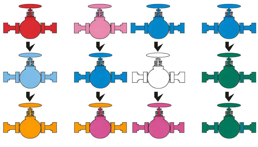
Common variations of pressure relief valve symbols arise due to differences in industry standards, specific application requirements, and regional practices. These variations can include distinctions in graphical representation such as the use of different arrow styles to indicate flow direction, additional notations specifying set pressure values, and symbols denoting specific types of pressure relief valves like spring-loaded or pilot-operated variants.
Certain industries may incorporate additional symbols to indicate the presence of auxiliary components like sensing lines or discharge piping. Variations can also be observed in the depiction of the valve's operational state, where symbols may show whether the valve is normally open or normally closed. Such distinctions ensure clarity and precision in technical documentation and schematics.
Industry Standards
Industry standards for pressure relief valve symbols provide an essential framework ensuring uniformity and accuracy in technical documentation across various sectors. These standards, such as those set by the International Organization for Standardization (ISO) and the American National Standards Institute (ANSI), prescribe specific graphical representations and annotations.
Compliance with these standards mitigates misinterpretation risks and facilitates seamless communication among engineers, manufacturers, and operators. The ISO 1219-1:2012 and ANSI/ISA-5.1-2009 guidelines detail the exact symbol configurations, including the depiction of inlet and outlet paths, actuator types, and set pressure indicators.
Adherence to these standards is crucial for maintaining system integrity, safety, and functionality, particularly in industries such as oil and gas, chemical processing, and aerospace engineering.
Interpreting Diagrams
Interpreting diagrams involves a thorough understanding of diagram symbols, which are standardized to guarantee consistency across technical drawings.
Reading technical drawings requires familiarity with conventions that represent various components, including pressure relief valves.
Accurate identification of valve components within these diagrams is essential for proper system analysis and troubleshooting.
Understanding Diagram Symbols
Understanding the symbols used in engineering diagrams is critical for accurately interpreting and analyzing system schematics. Diagram symbols serve as the universal language in engineering, allowing professionals to convey complex systems succinctly.
For instance, the symbol for a pressure relief valve typically includes a spring-loaded valve representation, indicating its function to release excess pressure. Accurate symbol interpretation guarantees proper system function analysis and troubleshooting. Misinterpretation can lead to erroneous conclusions and potential system failures.
Hence, familiarity with standardized symbols, such as those defined by ANSI or ISO, is indispensable. Additionally, cross-referencing legend keys and maintaining updated symbol libraries enhances the reliability and clarity of diagram interpretations, fostering effective communication among engineers.
Reading Technical Drawings
Accurate interpretation of technical drawings requires a thorough understanding of the standardized symbols and conventions that represent various components and processes within engineering systems. These symbols, governed by organizations such as ISO and ANSI, provide a universal language that promotes consistency and clarity.
To effectively read these drawings, one must be adept at recognizing symbols like those for pressure relief valves, which are essential for maintaining system safety. By analyzing line types, connection points, and annotations, professionals can precisely determine the function and interrelationships of components.
Mastery of these skills guarantees precise communication among engineers, designers, and technicians, thereby facilitating efficient system design, troubleshooting, and maintenance. Understanding the nuances of these diagrams is vital for successful engineering outcomes.
Identifying Valve Components
The process of identifying valve components in technical diagrams involves a meticulous examination of symbols, annotations, and schematic representations to guarantee accurate functionality and integration within the system.
Each symbol conveys specific attributes, such as valve type, actuation method, and flow direction. For pressure relief valves, the symbol typically includes a spring-loaded mechanism to indicate its primary function of pressure regulation.
Annotations provide additional details like set pressure points and material specifications. Accurate interpretation of these diagrams is critical for ensuring system safety and efficiency.
Analyzing the interplay between components, such as inlet and outlet connections, helps in understanding the overall system design, aiding in troubleshooting and maintenance tasks. Such precision is indispensable for engineering professionals and technicians alike.
Application in Systems
In system applications, the pressure relief valve serves as a critical safety component, preventing catastrophic failure by releasing excess pressure.
By maintaining ideal pressure levels, it greatly enhances system efficiency.
Additionally, the pressure regulation mechanism guarantees operational stability and prolongs equipment lifespan.
Critical Safety Component
How does the pressure relief valve function as a critical safety component in various industrial systems?
The pressure relief valve (PRV) is essential for maintaining system integrity by preventing overpressure conditions. In applications like chemical processing, oil and gas, and power generation, PRVs automatically release excess pressure when system thresholds are exceeded, thus avoiding catastrophic failures, equipment damage, and potential hazards to personnel.
System Efficiency Improvement
Beyond their role in guaranteeing safety, pressure relief valves greatly enhance system efficiency by maximizing pressure levels within industrial processes.
These valves mitigate pressure fluctuations, guaranteeing consistent operational parameters which reduce wear on system components and minimize energy consumption.
By maintaining ideal pressure, they prevent over-pressurization, which can lead to costly downtime and maintenance.
Additionally, pressure relief valves contribute to the efficient management of fluid dynamics, thereby enhancing the overall performance of hydraulic and pneumatic systems.
Their ability to release excess pressure at predefined setpoints ensures that the system operates within its design parameters, hence promoting longevity and reliability.
This maximization translates into lower operational costs and improved process continuity, making pressure relief valves invaluable for system efficiency.
Pressure Regulation Mechanism
Pressure relief valves employ sophisticated mechanisms to regulate and stabilize pressure within complex industrial systems. These valves utilize spring-loaded or pilot-operated designs to maintain predetermined pressure thresholds.
When system pressure exceeds the set limit, the valve actuates, allowing fluid or gas to escape, thereby preventing equipment damage and maintaining operational safety. The spring-loaded valve directly responds to pressure changes, while pilot-operated valves leverage auxiliary control systems for enhanced accuracy.
Advanced materials and precise engineering minimize hysteresis and guarantee rapid response times. Integration of pressure relief valves into hydraulic, pneumatic, and steam systems exemplifies their critical role in maintaining system integrity, reducing downtime, and enhancing reliability.
Understanding these mechanisms is crucial for optimizing system performance and ensuring safety compliance.
Safety Considerations
When designing and implementing pressure relief valves, it is essential to thoroughly consider safety factors to prevent equipment failure and maintain operational integrity.
Critical safety considerations include proper sizing of the valve to guarantee it can handle the maximum anticipated pressure without risk of rupture.
Material compatibility is crucial to withstand corrosive fluids and high temperatures.
Regular maintenance schedules and inspections are necessary to identify wear and tear, guaranteeing reliable performance.
Additionally, incorporating fail-safe mechanisms, such as redundant relief systems, enhances safety.
Adhering to relevant industry standards and codes, like ASME and ISO, ensures compliance and reduces risk.
Proper installation practices, including correct orientation and secure mounting, further mitigate potential hazards.
Troubleshooting Tips
Identifying and addressing common issues in pressure relief valves is crucial for maintaining their peak performance and safeguarding safety.
The first step in troubleshooting is to check for signs of leakage, which could indicate seat damage or improper sealing. Inspect the valve for corrosion or debris that may impede its operation.
Verify the set pressure and confirm it aligns with system specifications. If the valve fails to open at the designated pressure, there may be mechanical binding or spring fatigue.
A systematic approach to troubleshooting includes reviewing maintenance records, conducting pressure tests, and examining the valve's installation for alignment issues.
Employing these methods will guarantee the pressure relief valve operates reliably and mitigates potential hazards.
Conclusion
To sum up, grasping the symbol for a pressure relief valve is vital for interpreting engineering diagrams and guaranteeing system safety.
The fundamental design, while standardized, showcases differences across various industries. Following these standards guarantees clear communication and operational consistency.
Evaluating the precision of these symbols in diverse applications highlights their importance in averting system malfunctions and improving reliability.
Profound understanding of these symbols assists in efficient troubleshooting and maintenance, thereby strengthening system integrity and safety.