Symbol for Flow Control Valve: Identify it!
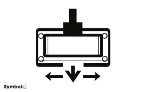
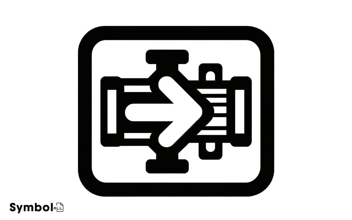
In hydraulic diagrams, you’ll spot the flow control valve symbol as a square with an arrow inside, pointing the fluid flow direction. This square encapsulates the valve body, important for illustrating fluid dynamics.
Variations exist; for precision control, an arrow slashes the square diagonally, while proportional valves add parallel lines next to the directional arrow. These symbols decode the valve’s operation, guiding you in adjusting flow and understanding the system’s efficiency.
Mastering these symbols equips you with insights into configuring and troubleshooting hydraulic systems more effectively. Grasping the nuances offers a step toward optimizing your hydraulic projects.
Key Takeaways
Understanding Flow Control Valves
To grasp flow control valves, it’s essential to understand that they regulate the rate and pressure of fluids in hydraulic systems, serving as critical components in managing fluid dynamics.
These valves adjust the flow volume and direction, ensuring ideal performance and protection of hydraulic circuits.
By manipulating the opening through which the fluid passes, they directly influence the speed of hydraulic actuators. This adjustment is crucial for applications requiring precise control over movement, such as in manufacturing equipment and mobile hydraulics.
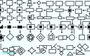
Referencing technical diagrams, you’ll often find these valves depicted with specific symbols indicating their function and operation within the system. Understanding these symbols is key to interpreting hydraulic schematics accurately.
However, the basic symbol explanation, which is a crucial starting point for decoding these diagrams, will be covered in the following section.
The Basic Symbol Explained
Understanding the basic symbol of a flow control valve is essential for accurately interpreting hydraulic schematics.
Here’s a quick guide to the core components of the symbol:
| Component | Description |
|---|---|
| Arrow | Indicates fluid flow direction. |
| Envelope | Represents the valve body. |
| Line | Shows the path of fluid flow. |
| Adjustable Element | Denoted by an arrow through a circle, indicates adjustability. |
This symbol serves as the foundation for understanding how flow control valves are represented in hydraulic systems. Each element within the symbol is vital for identifying the valve’s function and operation mode.
For a precise understanding, it’s important to familiarize yourself with these basic components before diving into more complex variations and configurations.
Variations of the Symbol
Now that you’re familiar with the basic components of a flow control valve symbol, let’s explore the various symbol variations that represent different functionalities and configurations within hydraulic systems.
Each variation is meticulously depicted in diagrams, ensuring you can identify specific features critical for proper system design and analysis.
For instance, an arrow within the valve symbol indicates flow direction, essential for understanding the valve’s operation. Adjustable flow control valves are represented by an arrow crossing the symbol diagonally, highlighting adjustability features.
Proportional flow control valves, on the other hand, incorporate a series of lines parallel to the arrow, signaling their capability to modify flow rates proportionally.
These symbols aren’t just arbitrary; they’re carefully designed to convey precise information about the valve’s function, ensuring you can accurately interpret hydraulic system diagrams.
Reading Schematic Diagrams
Mastering the art of reading schematic diagrams empowers you to decipher complex hydraulic system layouts with precision, focusing on how each flow control valve symbol integrates into the overall design.
Here’s how to approach these diagrams effectively:
- Identify Symbols: Recognize flow control valve symbols among others to understand their function within the system.
- Trace Lines: Follow the lines connecting symbols to see the flow path and relationships.
- Note Adjustments: Look for any adjustable or fixed settings on flow control valves indicated in the diagram.
- Assess Direction: Determine the direction of flow through valves to anticipate system operation.
Importance in System Design
Understanding the symbols for flow control valves in your schematic diagrams is essential for enhancing system efficiency and developing effective risk mitigation strategies.
You’ll see how these symbols represent the mechanisms that regulate flow rates, ensuring your system operates within its ideal parameters.
This knowledge allows you to preemptively address potential failures, safeguarding your design against unforeseen downtimes and losses.
System Efficiency Enhancement
Incorporating flow control valves within system design greatly boosts overall efficiency by optimizing fluid dynamics and reducing energy consumption.
Here’s how they achieve this:
- Essential in Fluid Control: By allowing precise adjustments in flow rates, these valves guarantee that each component receives the exact amount of fluid needed, minimizing waste.
- Energy Savings: Proper flow regulation directly translates to lower pump speeds and reduced power requirements, cutting down on energy bills.
- System Longevity: Regulating flow reduces the stress on pipes and machinery, leading to less wear and tear and extending the system’s lifespan.
- Enhanced Performance: Flow control valves help maintain ideal operating conditions, enhancing the performance of the overall system.
Understanding these aspects is vital for designing efficient systems that not only save resources but also offer improved functionality and reliability.
Risk Mitigation Strategies
Why should designers prioritize risk mitigation strategies in system design?
Implementing these strategies is vital for ensuring system longevity and reliability. When you integrate risk mitigation early in the design phase, you’re setting a foundation for a robust system capable of handling unexpected disruptions without significant downtime.
Consider the flow control valve symbol in system diagrams; it’s not just a representation but a critical point for applying risk mitigation techniques.
By analyzing potential failure modes associated with this valve, such as leakage or blockage, and designing with redundancy or fail-safe mechanisms, you significantly reduce the system’s vulnerability.
Therefore, incorporating precise risk assessment and mitigation strategies around key components like flow control valves is essential for maintaining operational integrity and minimizing costly downtime.
Troubleshooting With Symbols
When troubleshooting flow control systems, recognizing and interpreting valve symbols is essential for identifying issues efficiently.
Here’s how you can leverage symbols to streamline the process:
- Identify the Type: Look for the basic shape to determine if it’s a gate, globe, check, or ball valve. Each has a distinct symbol.
- Check the Flow Direction: Arrows or triangles within the symbol indicate flow direction, important for understanding system functionality.
- Assess Actuation Method: Symbols include details on manual, pneumatic, or electric actuation. This informs you about the control mechanism.
- Look for Special Features: Additional marks or symbols denote features like pressure relief, which could be crucial in diagnosing system behavior.
Future Trends in Symbol Usage
As the world of engineering evolves, so too does the complexity and sophistication of valve symbols, demanding more precise interpretations and applications in flow control systems.
You’ll find that future trends lean towards integrating digital representations and augmented reality (AR) for real-time symbol analysis.
This means you’ll be interacting with symbols not just on paper or screens but in three-dimensional space, overlaying physical components.
It’s important to familiarize yourself with software that can interpret these symbols dynamically, offering insights into flow characteristics and potential system inefficiencies.
Additionally, expect symbols to accommodate more data, such as material specifications and pressure ratings, directly within their design.
This evolution necessitates a deeper understanding of diagram conventions and the ability to rapidly adapt to new symbol interpretations within your engineering practices.
Conclusion
To sum up, mastering the art of deciphering the enigmatic symbols of flow control valves is akin to unraveling the very secrets of the universe. Each twist and turn in their design holds the potential to revolutionize system efficiency.
As you pore over schematic diagrams, let each symbol be a beacon guiding you through the labyrinth of engineering marvels. This knowledge isn’t just power; it’s the cornerstone of innovation in system design, transforming mere mortals into masters of mechanical manipulation.
Remember, the future of symbol usage in technical schematics is as boundless as the stars, promising domains of possibilities yet to be explored.

