How to Identify the Symbol for a Gate Valve in Engineering Diagrams
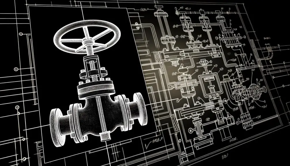
The symbol for a gate valve in technical diagrams, particularly Piping and Instrumentation Diagrams (P&IDs), consists of a rectangle intersected by two perpendicular lines. This standardized representation indicates a valve controlling fluid flow by lifting a gate.
Variations in the basic design include annotations for valve orientation, actuation methods, and operational status. Gate valves are critical for system isolation with minimal pressure drop.
Adherence to industry standards like API 600 and ISO 10434 guarantees reliability. Understanding these symbols is crucial for engineers and technicians to ensure efficient and accurate communication within systems.
There's more to explore for detailed understanding.
Key Takeaways
- A gate valve symbol typically consists of a rectangle intersected by two perpendicular lines.
- The symbol is essential for indicating gate valves in Piping and Instrumentation Diagrams (P&IDs).
- Variations of the symbol include additional elements like actuator symbols to denote operation type.
- The standard symbol helps distinguish gate valves from ball, globe, and butterfly valves.
- Industry standards like API 600 ensure consistent symbol representation for accurate communication among engineers.
Gate Valve Symbol Basics
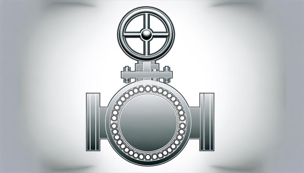
The gate valve symbol is a standardized graphical representation used in technical diagrams to denote a valve that controls fluid flow by lifting a gate out of the path of the fluid. This symbol is essential in piping and instrumentation diagrams (P&IDs) for accurately conveying valve type and function.
Typically, the gate valve symbol consists of a rectangle intersected by two perpendicular lines, representing the gate and its movement within the valve body. It is vital for ensuring proper communication among engineers, designers, and operators.
The precise depiction of the gate valve symbol aids in the systematic planning and troubleshooting of fluid systems, making it indispensable in various industries, including oil and gas, water treatment, and chemical processing.
Components of the Symbol
The components of the gate valve symbol are essential for accurately representing its function and characteristics in technical diagrams.
The basic symbol design typically includes a rectangle with a vertical line, indicating the gate's position within the valve body.
Additional symbol elements may incorporate annotations or specific markings to denote various features such as valve orientation, actuation method, and operational status.
Basic Symbol Design
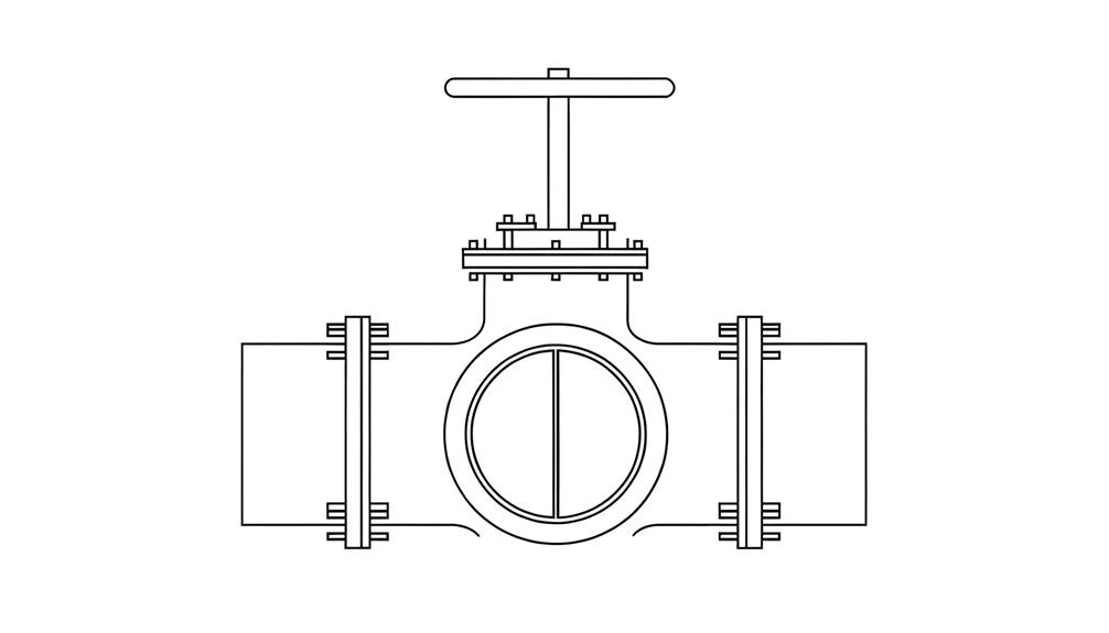
A gate valve symbol typically consists of a rectangular form intersected by a line, representing the gate or barrier inside the valve. This basic layout is a crucial graphical representation used in piping and instrumentation diagrams (P&IDs) to indicate the presence and functionality of a gate valve within a system. The rectangular form signifies the valve body, while the intersecting line denotes the internal gate that moves to open or close the flow path.
To illustrate:
| Component | Description |
|---|---|
| Rectangular Form | Represents the valve body |
| Intersecting Line | Symbolizes the gate or barrier within the valve |
| Vertical Alignment | Indicates the standard positioning of the valve symbol |
| Line Thickness | Denotes the scale and clarity of the symbol |
This precise configuration ensures precise and effective communication in technical documentation.
Additional Symbol Elements
Beyond the basic design, additional elements like actuator symbols, flow direction arrows, and connection indicators enhance the gate valve symbol's functionality and clarity.
Actuator symbols represent the type of actuator used, such as manual, pneumatic, or electric, providing vital operational information.
Flow direction arrows specify the intended flow path, ensuring correct installation and operation.
Connection indicators, including flanged, threaded, or welded connections, denote the method of attachment to the pipeline.
These elements, when incorporated, create a thorough and detailed diagram that aids in accurate valve specification and system design.
Properly annotated gate valve symbols serve as essential tools in technical drawings, facilitating communication among engineers, designers, and operators, and ensuring smooth integration within fluid control systems.
Common Variations
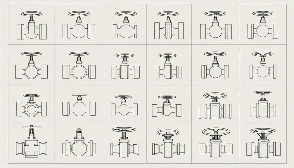
In the context of gate valve symbols, common variations pertain to manual operation types and automated valve options. Manual operation types typically include handwheel and lever-operated configurations, each represented by distinct graphical notations.
Automated valve options, such as electric or pneumatic actuators, are often denoted by supplementary symbols indicating the actuation method and control mechanisms.
Manual Operation Types
Manual gate valves are typically operated using one of three common variations: handwheel, lever, or chain wheel mechanisms. Each type has distinct advantages pertinent to specific applications.
Handwheel mechanisms, the most prevalent, utilize a rotary motion to open or close the valve, offering fine control over fluid flow.
Lever mechanisms allow for quick operation by moving the lever through a 90-degree arc, suitable for systems requiring frequent adjustments.
Chain wheel mechanisms are designed for valves installed at elevated or hard-to-reach locations, using a chain to transmit the turning motion.
Detailed diagrams of each mechanism illustrate their operational principles, ensuring accurate identification and application in system design and maintenance protocols.
Automated Valve Options
Automated gate valves offer enhanced control and efficiency through mechanisms such as electric actuators, pneumatic actuators, and hydraulic actuators, each providing distinct advantages tailored to specific industrial applications. Electric actuators are prized for their precision and ease of integration with digital control systems. Pneumatic actuators, operating via compressed air, are known for their rapid response times and reliability in hazardous environments. Hydraulic actuators, leveraging fluid power, excel in applications requiring substantial force.
| Actuator Type | Key Advantage | Typical Application |
|---|---|---|
| Electric Actuator | Precision | Automated control systems |
| Pneumatic Actuator | Rapid response | Hazardous environments |
| Hydraulic Actuator | High force capability | Heavy-duty industrial operations |
| Hybrid Actuator | Versatility | Mixed control environments |
| Smart Actuator | Data integration | IoT-enabled systems |
Understanding these variations aids in selecting the most suitable solution.
Interpreting the Symbol
Understanding the symbol for a gate valve requires familiarity with its standardized representation in engineering diagrams and technical schematics. The symbol typically consists of a straight line intersected by a perpendicular line, often enclosed within a circle or square. Correct interpretation ensures accurate system configuration and operational efficiency.
Key aspects to take into account include:
- Orientation: The perpendicular line signifies the gate mechanism, essential for understanding flow direction.
- Enclosure: The symbol may be encased in a circle or square, indicating specific operational characteristics.
- Annotations: Accompanying text or numerical labels denote valve specifications, such as size or material.
- Context: Placement within the schematic provides insight into its role within the overall system.
Precise comprehension of these elements is crucial for engineers and technicians.
Usage in P&IDs
In Piping and Instrumentation Diagrams (P&IDs), the gate valve symbol is necessary for indicating the presence and function of gate valves within the system. This symbol facilitates accurate communication among engineers and technicians, guaranteeing the correct implementation of the system's design. Gate valves are typically represented by a simple, distinctive symbol that clearly distinguishes them from other types of valves.
The usage of the gate valve symbol in P&IDs can be summarized as follows:
| Element | Description |
|---|---|
| Symbol | Represents a gate valve |
| Function | Controls flow by lifting or lowering a gate |
| Positioning | Placed along process lines in diagrams |
| Importance | Ensures precise system configuration |
Accurate representation of gate valves in P&IDs is essential for system reliability and efficiency.
Comparison With Other Valves
When comparing gate valves with other common valve types such as ball valves, globe valves, and butterfly valves, it is important to take into account their unique mechanisms and specific applications within a P&ID framework. The following points highlight key distinctions:
- Mechanism:
- Gate valves utilize a linear motion to control flow.
- Ball valves use a rotary motion with a spherical disc.
- Globe valves have a linear motion with a plug mechanism.
- Butterfly valves employ a rotary motion with a disc.
- Flow Control:
- Gate valves are ideal for on/off control.
- Ball valves offer tight sealing with quick operation.
- Globe valves provide precise throttling.
- Butterfly valves are suitable for large volume flow control.
- Pressure Drop:
- Gate valves have minimal pressure drop.
- Globe valves exhibit higher pressure drop.
- Ball and butterfly valves show moderate pressure drop.
- Applications:
- Gate valves: Isolation.
- Ball valves: Quick shutoff.
- Globe valves: Flow regulation.
- Butterfly valves: Large-scale flow.
Industry Standards
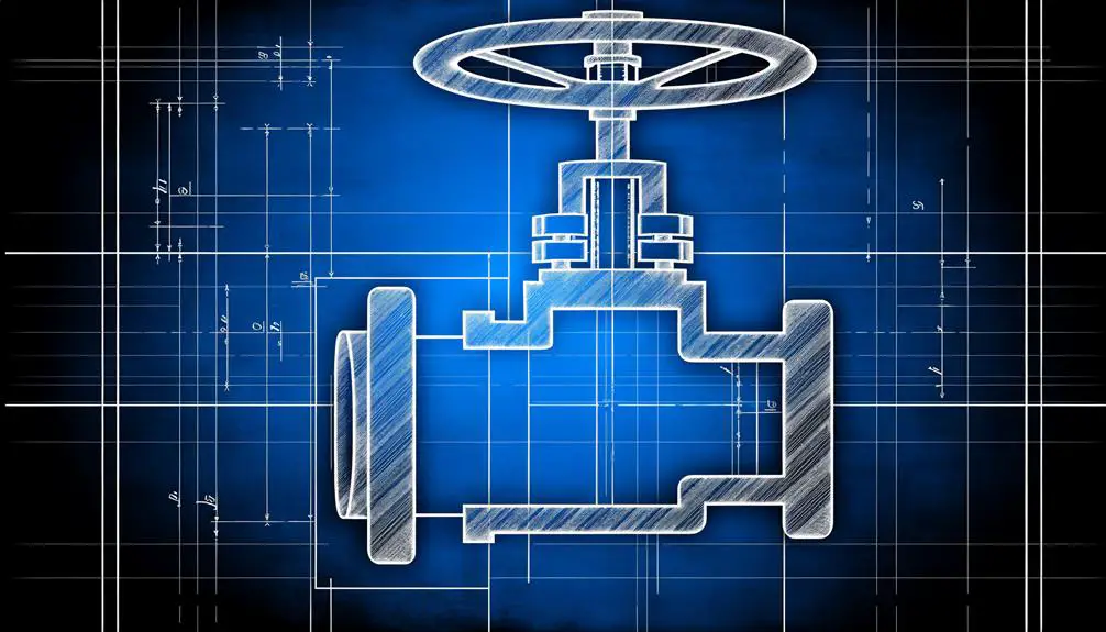
Adherence to industry standards is essential for ensuring the reliability and safety of gate valve applications in various industrial processes. Standards such as API 600 and ISO 10434 provide in-depth guidelines for valve design, manufacturing, and testing. These include specifications for materials, pressure ratings, and dimensions, ensuring interoperability and performance consistency.
Detailed diagrams in these standards illustrate the correct symbol representation, facilitating precise communication among engineers and technicians. Compliance with such standards mitigates risks associated with valve failure, optimizing operational efficiency and safety.
Gate valve symbols standardized by these guidelines are critical in process schematics, aiding in the accurate interpretation and implementation of industrial systems. Ensuring adherence to these standards underpins the successful deployment of gate valves in complex industrial environments.
Symbol in Different Systems
Different industrial systems utilize specific symbols for gate valves, ensuring clear and accurate representation in process schematics. These symbols vary depending on the standard or system being used, such as ANSI, ISO, or P&ID diagrams, and must accurately convey the function and type of valve.
- ANSI (American National Standards Institute): Utilizes a rectangular symbol with a vertical line through the center, representing the gate valve.
- ISO (International Organization for Standardization): Features a circular symbol intersected by two parallel lines, indicative of the gate mechanism.
- P&ID (Piping and Instrumentation Diagram): Depicts a gate valve with a simplified icon, typically a wedge within a circle.
- JIS (Japanese Industrial Standards): Uses specific symbols that may include additional notations to denote valve specifications.
These standardized symbols facilitate precise communication across various engineering disciplines.
Practical Applications

In practical applications, gate valves are integral components in processes requiring precise flow control, particularly in systems involving high-pressure fluids and gases. They are extensively used in industries such as oil and gas, water treatment, and power generation. Gate valves operate by lifting a gate out of the fluid path, providing unobstructed flow when fully open and tight sealing when closed. Below is a table illustrating common applications:
| Industry | Application | Key Benefit |
|---|---|---|
| Oil & Gas | Pipeline Isolation | High pressure tolerance |
| Water Treatment | Distribution Networks | Effective flow regulation |
| Power Generation | Steam Control | High-temperature resilience |
| Chemical | Process Isolation | Corrosion resistance |
These valves ensure efficient performance, reliability, and safety within various industrial systems.
Conclusion
To conclude, understanding the symbol for a gate valve is vital for accurate interpretation across various engineering documents, especially Piping and Instrumentation Diagrams (P&IDs).
The symbol comprises specific components and variations, each serving a distinct purpose. Familiarity with these symbols promotes effective communication and operational efficiency.
As the saying goes, 'the devil is in the details,' and attention to these specifics is crucial for maintaining industrial standards and ensuring smooth functionality in different systems.