How to Identify the Symbol for a Ball Valve in Engineering Diagrams
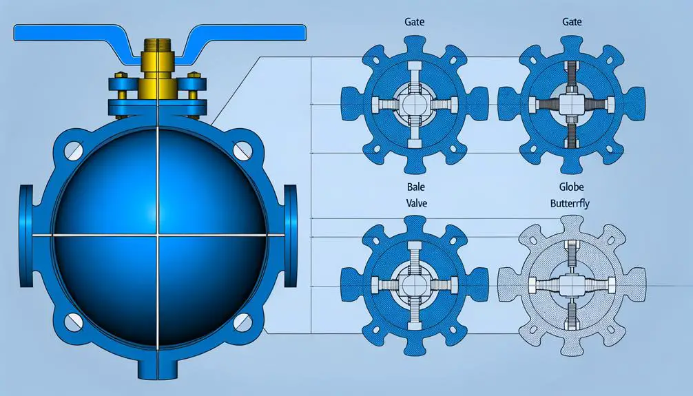
The symbol for a ball valve in Piping and Instrumentation Diagrams (P&IDs) is generally depicted as a circle with either a solid or hollow circle inside, representing the ball mechanism. Flow paths are indicated by lines passing through or around the symbol, guaranteeing clear visualization of valve function within the system.
Adherence to industry standards such as ISO 10628 and ANSI/ISA-5.1 ensures consistency. Engineers utilize these symbols for efficient system design and maintenance.
To master the integration of these symbols in complex piping systems, a more detailed exploration of the established standards and applications is essential.
Key Takeaways
- A ball valve symbol is typically a circle containing a solid or hollow circle representing the ball.
- Lines within the symbol indicate the flow path through the valve.
- Common standards like ISO 10628 and ANSI/ISA-5.1 provide uniform ball valve symbols.
- North American symbols use a segmented circle, while European standards may use a triangle within a circle.
- Mastery of these symbols enables efficient system design and maintenance in engineering.
Ball Valve Basics
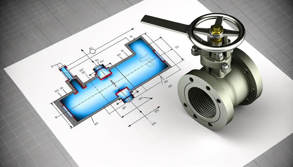
A ball valve is a quarter-turn valve that utilizes a hollow, perforated, and pivoting ball to control the flow of liquids or gases through a pipeline. The ball has a hole, known as a port, through its center, enabling flow when aligned with the pipeline.
When the ball is rotated 90 degrees by the valve handle, the port is perpendicular to the flow path, effectively blocking the fluid passage. This design provides robust sealing capabilities, ensuring minimal leakage.
Ball valves are favored for their durability, reliability, and ease of operation, making them suitable for a wide range of applications, including industrial processes, water treatment, and oil and gas sectors. Their simple construction results in low maintenance and long service life.
Identifying the Symbol
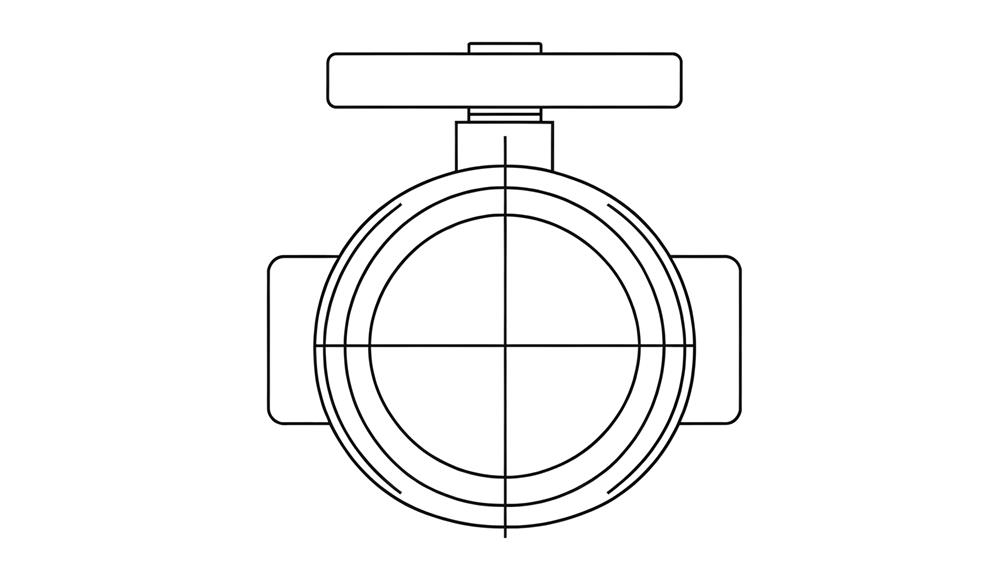
The symbol for a ball valve in piping and instrumentation diagrams (P&IDs) typically consists of a circle containing a solid or hollow circle, representing the ball, with lines indicating the flow path through the valve.
This visual representation is critical for understanding the function and position of the valve within a system. The outer circle denotes the valve body, while the internal circle signifies the ball component that controls fluid flow. Directional arrows or lines illustrate the operational state, either open or closed, ensuring precise interpretation.
Such detailed symbolism is essential for engineers and technicians, facilitating accurate communication and efficient system design. Mastery of these symbols enables seamless integration and maintenance of complex piping systems.
Symbol Variations
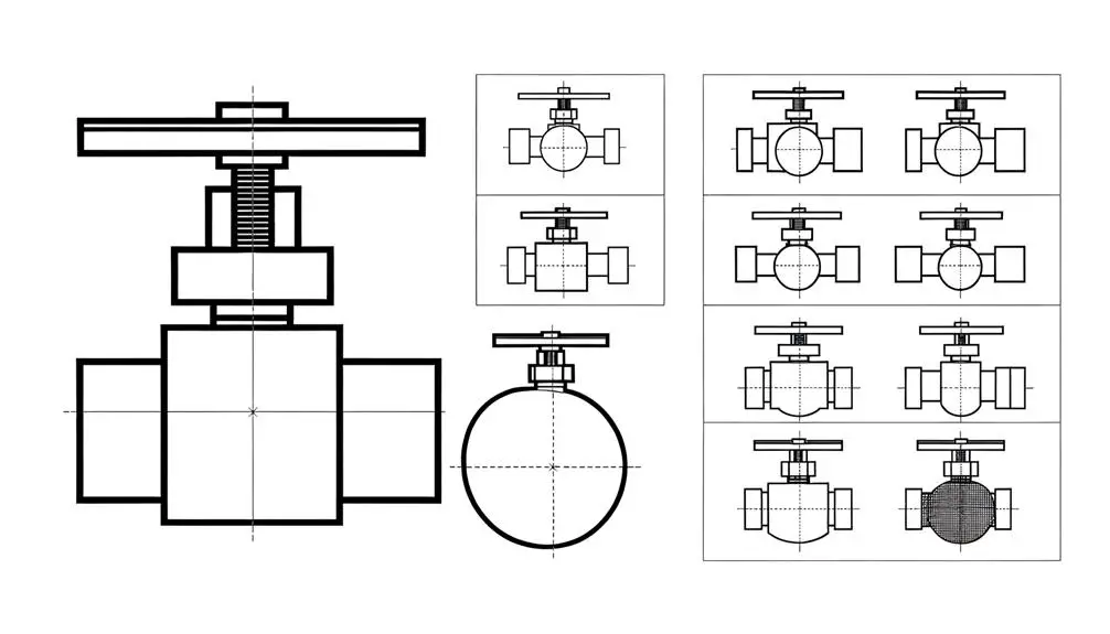
In the context of symbol variations for ball valves, it is essential to take into account both common industry standards and regional differences.
Industry standards, such as those set by ISO and ANSI, provide a uniform framework for symbol representation. However, regional discrepancies can lead to variations in symbols, necessitating awareness and adaptation for accurate interpretation in different geographical areas.
Common Industry Standards
Across various industries, ball valve symbols exhibit slight variations that conform to specific standards such as ISO 10628, ANSI/ISA-5.1, and DIN 30600. These standards guarantee that the symbols maintain a consistent level of readability and thoroughness across different technical drawings and documentation.
For instance, ISO 10628 focuses on creating universally recognizable symbols for process diagrams, while ANSI/ISA-5.1 emphasizes detailed instrumentation symbols used in control systems. DIN 30600, on the other hand, provides guidelines specific to German industrial practices.
Each standard incorporates unique graphical elements and annotations, ensuring that the ball valve symbols accurately convey their intended function and specifications within various applications. Adherence to these standards is essential for maintaining uniformity and avoiding misinterpretation in engineering projects.
Regional Symbol Differences
Variations in ball valve symbols can be observed across different regions, each influenced by local industry standards and practices.
In North America, the ANSI/ISA S5.1 standard often depicts ball valves with a segmented circle, representing the rotating ball mechanism.
Conversely, European standards, such as ISO 14617, typically use a simplified triangle within a circle to convey the same component.
In Asia, the JIS (Japanese Industrial Standards) may incorporate additional lines or annotations to specify valve orientation and function.
These discrepancies necessitate a thorough understanding of regional documentation to guarantee accurate interpretation.
Consequently, engineers and technicians must be adept at recognizing and translating these symbol variations to maintain consistency and accuracy in cross-border projects and engineering schematics.
Common Uses
Ball valves are integral components in various applications, each necessitating precise flow control and reliability.
In industrial settings, they are commonly used for managing the flow of gases and liquids, ensuring operational safety and efficiency.
Additionally, ball valves are prevalent in residential plumbing systems and HVAC systems, providing ease of operation and robust performance.
Industrial Applications
In industrial applications, ball valves are extensively utilized for their reliable sealing capabilities and ease of operation in high-pressure and high-temperature environments. These valves are pivotal to various sectors due to their robustness and efficiency.
Key industrial applications include:
- Oil and Gas: Ball valves control the flow of crude oil, natural gas, and refined products through pipelines.
- Chemical Processing: They are used to manage the flow of corrosive chemicals and ensure secure operations.
- Power Generation: Ball valves regulate steam and water flow in boilers and turbines.
- Pharmaceutical Manufacturing: These valves maintain sterile conditions by controlling the flow of fluids in drug production.
Their ability to handle diverse materials and conditions makes them indispensable across industries.
Residential Plumbing
Residential plumbing systems often utilize ball valves due to their simple mechanism and dependable shut-off capabilities, providing homeowners with control over water flow for maintenance and emergency situations. These valves, with a rotating sphere featuring a central bore, offer a quick and effective method for isolating sections of the plumbing network.
Commonly installed at main water inlets, branch lines, and fixture supply lines, ball valves guarantee minimal pressure drop and maximal flow rate when fully open. Their 90-degree turn operation allows for easy identification of the open or closed state, facilitating prompt action during leaks or repairs. Constructed from durable materials such as brass or PVC, ball valves demonstrate long-term resilience, making them a preferred choice in residential applications.
HVAC Systems
Utilized similarly in HVAC systems, ball valves play a pivotal role in regulating refrigerant flow and ensuring precise control over heating and cooling processes. These valves are integral to maintaining system efficiency and reliability.
Key applications in HVAC systems include:
- Chiller Units: Ball valves manage the flow of refrigerant, optimizing cooling capacity and energy efficiency.
- Air Handling Units: They control the distribution of conditioned air, ensuring consistent temperature regulation.
- Heat Pumps: Ball valves facilitate the reversal of refrigerant flow, essential for switching between heating and cooling modes.
- Cooling Towers: These valves regulate water flow, aiding in temperature control and system balance.
Their ability to provide tight shutoff, minimal pressure drop, and ease of operation make ball valves indispensable in HVAC applications.
Reading Schematics
Understanding the intricacies of reading schematics is crucial for accurately interpreting the function and placement of components such as ball valves in complex systems. Schematics convey essential information through standardized symbols and notations, guaranteeing uniform understanding across various engineering disciplines. Below is a table illustrating key symbols related to ball valves:
| Symbol | Description | Function |
|---|---|---|
|  | Ball Valve Symbol | Indicates a ball valve in a fluid system |
|  | Flow Direction | Shows the direction of fluid flow |
|  | Valve Position | Represents the open or closed state of the valve |
Accurate interpretation of these symbols guarantees proper system configuration, operational efficiency, and safety compliance.
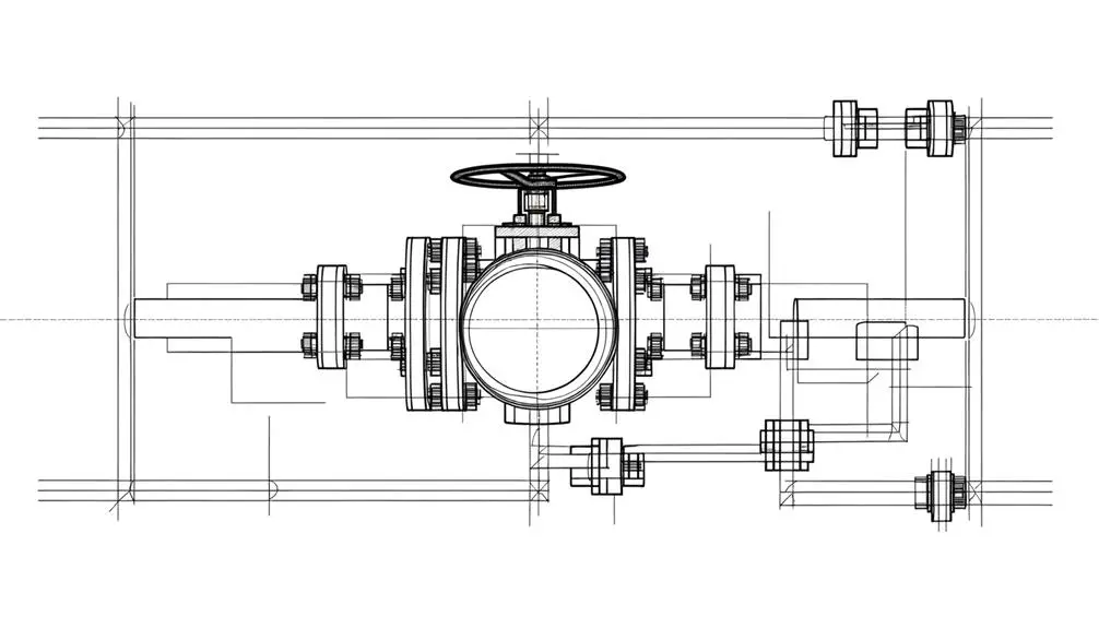
Importance in Engineering
The integration of ball valves into engineering systems is pivotal for ensuring precise control over fluid dynamics, enhancing both operational reliability and safety. Their significance is underscored by several significant factors:
- Flow Control: Ball valves provide precise modulation of flow rates, essential for maintaining optimal system performance.
- Durability: Constructed from robust materials, they offer longevity and resistance to wear and corrosion, reducing maintenance frequency.
- Leakage Prevention: Their design minimizes leakage potential, vital for systems requiring high integrity.
- Operational Simplicity: The straightforward mechanism ensures ease of operation and quick response times, essential for emergency shutdowns.
These attributes underscore the indispensability of ball valves in engineering, where precision and reliability are non-negotiable.
Differences From Other Valves
Ball valves distinguish themselves from other valve types through their unique mechanism, which employs a rotating spherical disc to control fluid flow. This design guarantees a reliable seal and minimal pressure drop compared to gate or globe valves.
Unlike butterfly valves that use a rotating disc, ball valves offer superior sealing capabilities and are less prone to leakage. Additionally, the quarter-turn actuation mechanism of ball valves provides rapid operation, contrasting with the multi-turn action required by gate valves.
Ball valves also handle high-pressure applications effectively, unlike diaphragm valves that are limited by their flexible membrane. The simplicity of the ball valve's construction results in lower maintenance requirements, making them ideal for applications requiring frequent operation and reliable performance.
Symbol Standards
Given the unique characteristics and operational benefits of ball valves, it is crucial to adhere to established symbol standards for accurate representation in technical diagrams and schematics. Symbol standards guarantee consistency and precision, facilitating clear communication among engineers and technicians.
Recognized standards include:
- ISO 1219: International standard for fluid power systems and components, specifying graphical symbols.
- ANSI/ISA S5.1: American standard for instrumentation symbols and identification, widely used in process control industries.
- DIN 2429: German standard providing graphical symbols for piping systems.
- JIS Z 8210: Japanese standard for graphical symbols in technical documentation.
These standards encompass specific shapes and annotations to denote ball valves, ensuring uniformity in design documentation and enhancing interpretability across global projects.
Practical Examples
Engineers often utilize specific examples from ISO 1219, ANSI/ISA S5.1, DIN 2429, and JIS Z 8210 to illustrate the correct application of ball valve symbols in technical schematics. These standards guarantee the consistent use of symbols, enhancing clarity and communication in technical drawings. Considerations include the representation of ball valves in different states (open, closed) and their integration into larger systems.
| Standard | Symbol Example | Application |
|---|---|---|
| ISO 1219 |  | General fluid power systems |
| ANSI/ISA S5.1 |  | Process industry diagrams |
| DIN 2429 |  | European hydraulic and pneumatic schematics |
| JIS Z 8210 |  | Japanese industrial equipment |
Understanding these practical examples guarantees accurate and effective communication in engineering documentation.
Tips for Beginners
When starting with ball valve symbols, it is essential to first comprehend the standard representations used in technical diagrams. Beginners should familiarize themselves with the distinctive features of ball valves, such as the spherical closure unit and directional flow markings.
Common mistakes often include misinterpreting these symbols, which can lead to significant design or operational errors.
Understanding Valve Symbols
Accurately interpreting valve symbols is crucial for anyone involved in the design, operation, or maintenance of fluid handling systems. These symbols act as a universal language, enabling clear communication across engineering disciplines.
To comprehend valve symbols effectively:
- Familiarize with Standard Symbols: Learn the standard symbols used in Piping and Instrumentation Diagrams (P&IDs), such as those defined by ISO or ANSI.
- Identify Symbol Components: Recognize the different parts of a symbol, including the actuator type, valve body, and flow direction.
- Contextual Interpretation: Consider the surrounding pipework and instrumentation to precisely deduce the valve's function.
- Reference Documentation: Utilize technical manuals and standards documents for precise symbol definitions and applications.
Mastering these elements guarantees precise interpretation and efficient system management.
Identifying Ball Valve Features
A ball valve features a spherical closure unit that rotates to control the flow of liquid or gas through a pipeline. This unit includes a bored-through ball encased within a housing, allowing for precise flow regulation.
The position of the ball, determined by a lever or actuator, dictates the flow state—open, closed, or throttled. Ball valves are characterized by their low torque requirements, quick shutoff capability, and minimal pressure drop.
Materials for construction typically include stainless steel, brass, or PVC, selected based on application needs. Additionally, ball valves come in various configurations, such as floating, trunnion-mounted, and multi-port designs, each suited for specific functional requirements.
Understanding these features ensures optimal selection and application.
Common Beginner Mistakes
For those new to ball valves, one common mistake is neglecting the material compatibility with the specific media being controlled. Ensuring that the valve material is suitable for the media prevents corrosion and degradation.
Here are other prevalent beginner errors:
- Incorrect Sizing: Choosing a valve size based on pipe diameter alone without considering flow requirements may lead to inefficiencies.
- Improper Installation: Failing to follow manufacturer guidelines can result in leaks or operational failures.
- Overlooking Pressure Ratings: Using a valve with an inadequate pressure rating can lead to catastrophic failure.
- Ignoring Maintenance Needs: Neglecting regular maintenance can reduce the valve's lifespan and performance.
Avoiding these common mistakes enhances the operational integrity and longevity of ball valves.
Conclusion
To wrap up, the symbol for a ball valve serves as a critical element in various industrial schematics, providing a standardized means of communicating complex information.
It is worth noting that ball valves account for approximately 20% of valves used in industrial applications, underscoring their widespread utility.
Mastery of identifying and interpreting these symbols facilitates accurate schematic readings, ensuring efficient and effective system design and maintenance.
Understanding the subtle differences between valve symbols further enhances technical proficiency and operational success.