Symbol for 3rd Angle Projection: What Does It Represent?
The symbol for 3rd angle projection, standardized by ISO 5456-2 and ASME Y14.3, is integral to technical drawings. It comprises a truncated cone for clear orientation of views, guaranteeing accurate representation and minimizing misinterpretation.
This symbol precisely denotes that the object's view placement follows the 3rd angle projection method, widely adopted in the United States and Canada. Consistent and correct use of this symbol fosters clear communication and reduces errors in design interpretation, facilitating seamless collaboration across disciplines.
Understanding its usage and differences from other projection methods assures precision in technical documentation. Learn more to enhance your technical drawing skills.
Key Takeaways
- The 3rd angle projection symbol is standardized and recognizable internationally.
- It depicts a truncated cone with a larger circle on the left and a smaller circle on the right.
- Adherence to this symbol ensures clear and accurate technical communication.
- The 3rd angle projection symbol prevents design misinterpretations by indicating view orientation.
- Compliance with standards like ISO 5456-2 and ASME Y14.3 ensures consistency in drawings.
Understanding Projection Methods
Projection methods in technical drawing are crucial techniques used to represent three-dimensional objects on two-dimensional media accurately. These methods are fundamental in ensuring that the spatial relationships and dimensions of an object are conveyed precisely.
Orthographic projection is a primary technique, involving multiple views of an object from different angles—typically the front, top, and side views. This method allows for detailed and unambiguous representation, critical in engineering and architectural drawings.
Axonometric projections, such as isometric, dimetric, and trimetric projections, offer a pseudo-3D view by distorting angles but maintaining scale. Each method serves specific needs, ensuring clarity and accuracy in technical documentation.
Understanding these methods is essential for producing reliable and interpretable technical drawings.
Importance of Projection Symbols
Projection symbols, such as the one for 3rd angle projection, are vital for ensuring standardization and facilitating global understanding in technical drawings.
These symbols prevent design misinterpretations by providing a clear and universally recognized method for representing three-dimensional objects on two-dimensional media.
Consequently, their proper use is essential for maintaining consistency and accuracy across international engineering and manufacturing practices.
Standardization and Global Understanding
The standardization of projection symbols is critical for ensuring global comprehension and consistency in technical drawings. By adhering to internationally recognized standards, such as those established by ISO and ANSI, professionals across various industries can accurately interpret and communicate design intentions.
These standardized symbols eliminate ambiguities, ensuring that a drawing produced in one country can be understood in another without misinterpretation. The 3rd angle projection symbol, for instance, is universally recognized, allowing engineers, manufacturers, and designers to collaborate seamlessly.
This uniformity is indispensable in a globalized market where products are often designed, manufactured, and assembled in different parts of the world. Consequently, standardized projection symbols facilitate precise and efficient technical communication, fostering innovation and reducing costly errors.
Preventing Design Misinterpretations
Accurate interpretation of technical drawings hinges on the use of standardized projection symbols, which play an essential role in preventing design misinterpretations. The 3rd angle projection symbol, in particular, ensures clarity by indicating the method of visualization used in the drawing. This standardized approach eliminates confusion and enhances communication across global engineering teams.
To understand the importance:
- Consistency: Essential for ensuring all stakeholders interpret the drawing uniformly, reducing errors.
- Efficiency: Saves time by providing a clear visual reference, minimizing the need for additional explanations.
- Compliance: Adheres to international standards, facilitating collaboration and regulatory approval.
- Accuracy: Guarantees precise representation of component views, crucial for manufacturing and assembly.
Thus, the use of standardized projection symbols is indispensable in modern technical drawing practices.
3rd Angle Projection Explained
To elucidate the concept of 3rd angle projection, it is important to first comprehend the standardized projection symbols that differentiate it from other methods. These symbols serve as a critical element in ensuring uniformity and clarity across technical drawings.
Additionally, adherence to specific drawing layout guidelines is necessary for accurately representing spatial relationships and dimensions in 3rd angle projection.
Understanding Projection Symbols
Understanding projection symbols is crucial for accurately interpreting technical drawings, as these symbols provide essential information about the orientation and view of the object being depicted. Projection symbols serve as a universal language in technical documentation, guaranteeing that engineers, designers, and manufacturers can effectively communicate complex geometries. These symbols are standardized to eliminate ambiguity and enhance comprehension.
Key aspects of projection symbols include:
- View Orientation: Indicates the direction of the view in relation to the object.
- Projection Method: Defines whether the drawing uses first-angle or third-angle projection.
- Symbol Representation: A graphical symbol that represents the projection method used.
- Standard Compliance: Guarantees adherence to international standards such as ISO or ANSI.
These elements collectively enable precise and unambiguous technical communication.
Drawing Layout Guidelines
Building on the foundational knowledge of projection symbols, drawing layout guidelines for third-angle projection are crucial for creating coherent and standardized technical drawings.
In third-angle projection, the object is imagined to be positioned in the third quadrant, resulting in the views being projected onto planes located behind and below the object.
Adherence to layout guidelines ensures that the front view is positioned centrally, with top, side, and auxiliary views placed consistently relative to the front view.
Dimensions, annotations, and scales must be meticulously applied to maintain clarity and precision. Utilizing standardized title blocks and revision tables further enhances the legibility and uniformity of the drawing.
This disciplined approach aids in effective communication among engineers, designers, and manufacturers.
Recognizing the Symbol
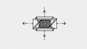
The symbol for 3rd angle projection is characterized by a truncated cone and a circle, positioned to distinctly indicate the method of orthographic representation used in technical drawings. This notation is essential for engineers and draftsmen to interpret the layout and viewpoints correctly.
Recognizing the symbol involves understanding its components and their arrangement:
- Truncated Cone: Represents the projection of a 3D object.
- Circle: Symbolizes the object's front view.
- Placement: The truncated cone is positioned above the circle, signifying the view sequencing.
- Standards Compliance: Adheres to ASME Y14.3 or ISO 5456 standards.
Differences From 1st Angle Projection
In contrast to the 3rd angle projection, the 1st angle projection method positions the object between the observer and the plane of projection, resulting in a different arrangement of views on the drawing sheet.
In the 1st angle projection, the top view is positioned below the front view, and the right-side view is placed to the left of the front view.
This reversal of view placement can initially confuse those familiar with the 3rd angle projection, where the top view is above and the right-side view is to the right.
These differences require careful attention to detail to avoid misinterpretations in technical drawings.
Understanding both methods guarantees accuracy in spatial representation and proper communication in international engineering practices.
Symbol Usage in Drawings
Understanding the symbol usage for 3rd angle projection is crucial for accurately interpreting and creating technical drawings in engineering and manufacturing. The symbol, typically represented by a truncated cone, indicates the projection method employed. Key considerations include:
- Placement: The symbol should be clearly positioned in the title block or near the drawing's key views.
- Orientation: Guarantee the truncated cone points appropriately, with the base at the left and the smaller end at the right.
- Consistency: Maintain uniform symbol usage across all drawings to avoid misinterpretation.
- Clarity: Use standardized symbols that are easily recognizable and comply with technical drawing conventions.
Adhering to these principles guarantees precision in communication and minimizes errors in the design and manufacturing processes.
Industry Standards and Practices
Adherence to industry standards and practices guarantees uniformity and precision in technical drawings across various engineering and manufacturing disciplines. The use of standardized symbols, such as the symbol for 3rd angle projection, guarantees that all stakeholders interpret drawings unequivocally.
Standards like ISO 5456-2 and ASME Y14.3 delineate the exact specifications for these symbols, promoting consistency. This uniformity is vital for seamless communication between engineers, manufacturers, and quality assurance teams. Compliance with these standards minimizes errors, reduces ambiguities, and enhances the efficiency of production processes.
The global adoption of these practices underscores their importance in facilitating international collaboration and ensuring that technical drawings meet universally accepted criteria for accuracy and clarity.
Benefits of Consistent Symbol Use
The observance of industry standards not only promotes uniformity but also brings forth significant benefits, such as the consistent use of symbols, which is crucial for clear and efficient communication in technical drawings. Consistency in symbol usage guarantees that all stakeholders, from engineers to manufacturers, interpret the drawings correctly and without ambiguity. This practice enhances efficiency and minimizes errors.
Reduced Misinterpretation: Uniform symbols eliminate confusion, guaranteeing that all parties have a common understanding.
Enhanced Collaboration: Standard symbols facilitate seamless communication between multidisciplinary teams.
Improved Training: Standardized symbols simplify the learning process for new engineers and technicians.
Quality Assurance: Consistent symbols support stringent quality checks, guaranteeing compliance with design specifications.
These benefits underscore the critical role of standardized symbols in technical documentation.
Conclusion
To sum up, the symbol for 3rd angle projection serves as an essential beacon guiding the lost souls of engineering drawing. Without it, deciphering the intricate dance of orthographic views would be like finding your way through a maze blindfolded.
This emblem, engraved into the history of drafting standards, provides clarity amidst the chaos, ensuring that industry practices remain as consistent as the sunrise.
Therefore, reverence for this symbol is not just suggested; it is a requirement for order and precision.