What Is the Schematic Symbol for an LED Light?
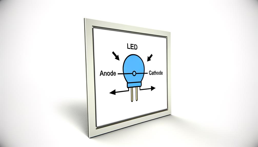
The schematic symbol for an LED light is a diode symbol with two arrows pointing away, indicating light emission. The symbol consists of a triangle pointing to a line, representing the flow of conventional current from the anode (positive side) to the cathode (negative side).
Variations exist, such as multi-color LEDs, which feature additional arrows or lines. Accurately interpreting this schematic symbol is critical for proper circuit design and performance.
Understanding further complexities, such as bi-color and infrared LED variations, will greatly enhance your circuit design skills and troubleshooting effectiveness.
Key Takeaways
- The LED symbol includes a diode with two arrows indicating light emission direction.
- The triangle and line represent the anode (positive) and cathode (negative) terminals.
- Correct LED polarity is crucial; anode connects to the positive, cathode to ground.
- Variations like bi-color LEDs use multiple arrows or segmented lines in their symbols.
- Flashing LEDs have annotations for their blinking frequency in the schematic symbol.
Understanding LED Symbols
Understanding LED symbols necessitates a comprehensive understanding of the standardized schematic representations utilized in electronic circuit diagrams.
The LED, or Light Emitting Diode, is symbolized by a diode symbol with two arrows pointing away, indicating the emission of light.
The diode portion consists of a triangle pointing to a line, denoting the direction of conventional current flow from anode to cathode.
The arrows represent the light emitted when the diode is forward biased.
It is vital to correctly interpret this symbol to guarantee proper integration into circuits, facilitating functions such as current control and signal indication. Misinterpretation may result in incorrect circuit design, impacting overall performance and reliability.
Hence, mastery of these symbols is essential for adept circuit design.
Common Variations
Beyond the basic LED symbol, several common variations exist to denote different types of LEDs and their specific functionalities within a circuit.
For instance, bi-color and tri-color LEDs are represented by symbols featuring multiple arrows or segmented lines, indicating their multi-wavelength capabilities.
Flashing LEDs, designed to blink at a fixed frequency, are often depicted with additional annotations highlighting this unique behavior.
Infrared LEDs, used in remote controls, are typically marked with a wavelength specification, distinguishing them from visible light LEDs.
Lastly, high-power LEDs, which require heat dissipation, might include heat-sink symbols or additional pins in their schematic representation. Recognizing these distinctions is vital for accurate circuit design and guarantees the correct implementation of light-emitting components.
Interpreting Circuit Diagrams

Interpreting circuit diagrams necessitates a significant understanding of each symbol and its corresponding function within the electrical system, ensuring accurate analysis and effective troubleshooting.
Recognizing the schematic symbol for an LED light—a diode symbol with arrows pointing away—enables precise identification of its role and orientation in the circuit. The polarity of the LED is crucial; the anode connects to the positive supply, and the cathode connects to the ground.
Additionally, understanding associated components such as resistors used to limit current is essential. Proficiency in reading these diagrams involves not just symbol recognition but also comprehension of the circuit's operational logic, allowing for systematic diagnosis and resolution of potential issues.
This analytical approach is important for maintaining circuit functionality and integrity.
Practical Applications
Accurate interpretation of circuit diagrams lays the foundation for the practical applications of LED lights in various electronic and electrical systems. LEDs are integral in numerous domains, including consumer electronics, automotive lighting, and industrial automation. Their inclusion in circuit designs enhances efficiency, reduces energy consumption, and increases longevity. Below is a table illustrating typical applications, benefits, and examples of LED integration:
| Application | Benefits | Examples |
|---|---|---|
| Consumer Electronics | Energy-saving, long-lasting | Televisions, smartphones |
| Automotive Lighting | Brightness, durability | Headlights, interior lights |
| Industrial Automation | Easy upkeep, dependable | Indicator lights, status displays |
The precise placement and interpretation of LED symbols in circuit diagrams facilitate seamless integration, ensuring top-notch performance across applications.
Troubleshooting Tips

When diagnosing issues with LED circuits, it is important to systematically verify connections, component integrity, and power supply stability to identify and resolve potential malfunctions efficiently.
Begin by inspecting all solder joints and wire connections for continuity and secure attachment. Utilize a multimeter to measure voltage and current levels, ensuring they align with the LED's specifications. Check the integrity of resistors, capacitors, and other circuit elements, replacing any that exhibit signs of wear or damage.
Additionally, confirm the power supply is delivering consistent voltage without fluctuations. If the LED remains unilluminated, consider the possibility of a reverse polarity connection or an internal LED failure. Documenting each step can facilitate a methodical troubleshooting process.
Conclusion
The schematic symbol for an LED light, with its arrow piercing through the darkness, is a beacon for understanding electronic circuits. Mastery of this symbol, alongside its variations and applications, illuminates the pathway to proficient circuit design and troubleshooting.
By methodically interpreting circuit diagrams, one can navigate the intricate web of connections with precision. Ultimately, this knowledge serves as a cornerstone for both novice and seasoned engineers in the ever-evolving field of electronics.