Process Flow Diagram Symbols PFD: Explains!
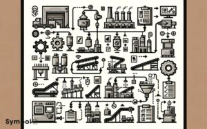
You’ll encounter various symbols on process flow diagrams , each representing equipment, processes, and flows standardized across the industry.
Mastering these symbols, from pumps and valves to tanks and compressors, is essential for understanding material and energy flow within chemical plants or refineries.
Symbols for piping and connections, necessary for showing physical elements, alongside instrumentation identifiers for measuring devices, play an important role. Also, familiarizing yourself with safety and alarm symbols guarantees operational safety.
A symbol legend often accompanies PFDs, decoding these representations for quick identification and comprehension, setting the stage for efficient process analysis and design insights.

Key Takeaways
17 Symbols of Process Flow Diagram (PFD)
| Symbol | Name | Description |
|---|---|---|
| O | Circle | Represents an operation or inspection point in a process. |
| △ | Triangle | Indicates a storage area or queue where materials or products wait before the next process step. |
| ▢ | Square | Denotes a process step, such as a task or activity. |
| ○ | Open Circle | Signifies a point of measurement or monitoring within the process. |
| → | Arrow | Shows the flow direction or sequence of operations within a process. |
| ╂ | Fork/Junction | Illustrates a process split where operations may proceed to multiple paths. |
| ∇ | Inverted Triangle | Indicates a filter or a separation process. |
| Ɑ | D-Shaped Symbol | Commonly used to denote a delay or waiting period in the process. |
| ⧈ | Converging Arrows | Shows where multiple process streams come together into a single path. |
| ⧋ | Diverging Arrows | Represents a decision point where a process can follow one of multiple paths. |
| ( ) | Ellipse | Typically used to represent the start or end of a process, also known as a terminator. |
| * | Asterisk | Sometimes used to mark a critical operation or a point of emphasis in the process. |
| XXX | Crossed Rectangles | Symbolizes a major process step that is a part of the main process flow. |
| Δ | Delta | Used to represent a change in the process or an adjustment. |
| Ω | Loop Symbol | Indicates a process loop or a repeat cycle within the process. |
| ⬈ | Diagonal Arrow | Can indicate a transfer to a different process or a change in the process path. |
| /// | Striped Lines | Often denotes a process or operation that is not within the immediate control of the organization (external operation). |
Understanding PFD Symbols
To effectively read and interpret Process Flow Diagrams (PFDs), you must first familiarize yourself with the various symbols used to represent equipment, processes, and flows.
These symbols, standardized across the industry, serve as the language of process design and engineering.
Understanding these symbols is vital for analyzing the operational aspects of a chemical plant or refinery.
Each symbol in a PFD represents a different component of the process, such as pipes, valves, and instruments, and their interactions.
Mastery of this symbolic language enables you to grasp the flow of materials and energy through various process units.
It’s imperative to approach these diagrams with a keen eye for detail, recognizing that each symbol conveys specific information about the process conditions and requirements.
Basic Equipment Symbols
Next, you’ll become familiar with basic equipment symbols, an essential component of process flow diagrams (PFDs).
You’ll learn to recognize common equipment icons, which serve as the building blocks for understanding complex diagrams.
Additionally, we’ll provide you with tips for accurate symbol interpretation, ensuring you can read and construct PFDs effectively.
Common Equipment Icons
Understanding common equipment icons is vital for accurately interpreting process flow diagrams. These symbols represent the various components and processes within a system.
This table is a starting point. Each icon is a building block, understanding them will enable you to grasp the overall design and operation of industrial processes.
Remember, precision in recognizing these symbols is essential for effective communication and analysis in engineering and related fields.
Symbol Interpretation Tips
Before delving into the nuances of symbol interpretation, it’s essential you’re familiar with the basic equipment icons used in process flow diagrams.
Each symbol represents a different piece of industrial equipment or process step, and mastering their meanings is vital for understanding the flow of operations within a facility.
Pumps, valves, compressors, and heat exchangers, for example, have distinct symbols that are universally recognized in the engineering world. When interpreting these symbols, pay attention to the details.
Small variations can signify different types or functions of equipment. For instance, a slight change in the symbol for a valve might indicate a different method of operation or control.
Familiarizing yourself with these subtleties enables you to read and comprehend complex diagrams efficiently.
Symbols for Valves
You’re now moving into the domain of valve symbols, a vital component in process flow diagrams.
Understanding the variety of valve symbol types is necessary for accurately depicting their functions within a system.
We’ll explore how these symbols represent different valve functions, enhancing your ability to read and design process diagrams effectively.
Valve Symbol Types
In process flow diagrams, valve symbols represent the various types of valves used to control flow, each with its unique design and function.
You’ll encounter symbols for gate valves, characterized by their linear motion to start or stop flow, providing a clear path when open.
Globe valves, depicted with their spherical bodies, regulate flow by changing the path’s direction, offering precise control.
Check valves, illustrated with a simple check mark or an angled line, allow flow in one direction, preventing backflow.
Ball valves use a circular symbol, indicating their ability to provide quick and reliable shutoff with a rotational motion. Butterfly valves, shown with a ‘T’ in a circle, offer flow control with minimal pressure drop.
Each symbol is meticulously designed to convey specific information about the valve’s operation, ensuring accurate interpretation and application in engineering documentation.
Valve Function Representation
Having explored various valve symbols and their unique designs, let’s now focus on how these symbols specifically represent valve functions in process flow diagrams.
Each symbol is meticulously designed to convey precise information about valve operation, orientation, and control mechanism.
For instance, a gate valve is depicted by a simple gate symbol, signifying its function as a straight-through pathway that can be completely opened or closed.
Similarly, a check valve is represented by a single swing check, illustrating its role in preventing backflow. Ball valves feature a solid circle, denoting their capability for multi-directional flow control.
Understanding these symbols allows you to swiftly interpret valve functions within a process, ensuring accurate and efficient communication and design within the engineering field.
Piping and Connection Icons
Understanding piping and connection icons is crucial for accurately interpreting process flow diagrams.
These symbols represent the physical elements of a system, such as pipes, hoses, and tubes, that transport materials between equipment.
A solid line typically depicts a pipe that carries liquids or gases. Dashed lines, in contrast, may indicate connections that aren’t permanent or are less significant in the process flow.
Elbows, tees, and reducers are shown with standardized shapes, allowing you to quickly grasp how the system components connect and interact.
Additionally, arrows often indicate the direction of flow, providing insight into the operational sequence.
Familiarizing yourself with these icons ensures you can effectively analyze and communicate about the process being diagrammed, enhancing both understanding and efficiency in design or troubleshooting tasks.
Instrumentation Identifiers
You’ll need to familiarize yourself with instrumentation identifiers, as they’re important symbols representing the various measuring devices and controls within a process flow diagram.
These identifiers are essential for understanding how measurements are taken, controlled, and adjusted throughout the process.
Typically, they consist of a combination of letters and numbers, each detailing the type of instrument, its location, and its function within the system.
For instance, a pressure gauge might be denoted as ‘P’ for pressure, followed by a unique identifier indicating its specific location or sequence in the process.
Similarly, temperature sensors, flow meters, and level gauges have their distinct symbols, like ‘T’ for temperature, ‘F’ for flow, and ‘L’ for level, respectively.
Mastering these identifiers is vital for accurately interpreting process flow diagrams and ensuring efficient operation.
Process Flow Directions
After familiarizing yourself with instrumentation identifiers, it’s important to explore how process flow directions guide the movement and management of materials within a system.
These directions are visually represented by arrows or lines on process flow diagrams (PFDs), indicating the path materials take from one process unit to another.
Understanding these directions is vital for comprehending the overall process and for troubleshooting issues that may arise.
The arrows’ orientation on the PFD symbolizes the flow’s direction, whether it’s moving towards processing units, storage tanks, or waste management systems. It’s crucial to accurately interpret these symbols to guarantee the efficiency and safety of the process.
Grasping the flow directions will also help you better understand the interactions between different process units and the system’s dynamics.
Heat Exchangers and Coolers
Heat exchangers and coolers play an important role in regulating temperatures within industrial processes, ensuring materials are conditioned precisely for best efficiency and safety.
You’ll find these components represented in process flow diagrams (PFDs) by specific symbols, which are critical for understanding the thermal management within a system.
Heat exchangers facilitate the transfer of heat between two or more fluids without mixing them, optimizing process temperatures. Coolers, on the other hand, remove excess heat, maintaining the desired temperature levels.
Recognizing these symbols in PFDs allows you to grasp the thermal regulation mechanisms in place, ensuring safe and efficient process operations.
It’s crucial to familiarize yourself with these symbols, as they’re foundational to interpreting and designing industrial systems effectively.
Pumps and Compressors
Shifting our focus to pumps and compressors, it’s essential to grasp that these components serve as the heart of many industrial systems, pushing fluids and gases through the process flow.
In process flow diagrams, you’ll encounter symbols that specifically represent:
- Centrifugal Pumps: Indicated by a circle with a small triangle pointing outwards, symbolizing their role in moving liquids through systems using centrifugal force.
- Positive Displacement Pumps: Depicted as a circle with a rectangle inside, highlighting their function in displacing a fixed amount of fluid with each cycle, essential for precise flow control.
- Compressors: Illustrated by a circle with a pair of crossed lines, signifying their use in increasing the pressure of gases by reducing volume.
Understanding these symbols allows for accurate interpretation of process flows, ensuring efficient and effective system design and operation.
Storage Tanks and Vessels
In the domain of process flow diagrams, storage tanks and vessels are symbolized by simple shapes that represent their essential role in holding liquids or gases until needed for further processing.
These symbols are important for you to understand as they convey specific types of storage units without cluttering the diagram with intricate details.
| Symbol | Description |
|---|---|
|  | Vertical storage tank |
|  | Horizontal storage tank |
|  | Spherical storage vessel |
|  | Gas storage balloon |
|  | Bin for solid materials |
Each symbol is designed for quick recognition, allowing you to grasp the layout and flow of a plant or process at a glance.
Understanding these symbols is crucial for interpreting diagrams accurately, ensuring you’re well-equipped to navigate the complexities of process flow diagrams.
Safety and Alarm Symbols
After understanding storage tanks and vessels, it’s important to focus on safety and alarm symbols which play a crucial role in ensuring operational safety and emergency preparedness in process flow diagrams.
These symbols are essential for identifying hazards, signaling potential safety issues, and guiding the response actions.
Here’s a concise overview:
- Pressure Relief Valve Symbol: Indicates a valve that automatically releases a substance when pressure exceeds a preset limit, ensuring system integrity.
- Flame Arrestor Symbol: Depicts a device that stops flame propagation, preventing fires and explosions in pipelines or storage tanks.
- Emergency Shower and Eyewash Symbol: Highlights safety equipment locations for immediate decontamination, critical for chemical exposure incidents.
Understanding these symbols is crucial for maintaining a safe operational environment and minimizing risks in process industries.
Symbol Legend and References
To effectively navigate process flow diagrams, you’ll need to familiarize yourself with the symbol legend and reference section, which catalogs all symbols used in the diagram for quick identification and interpretation.
This section serves as a key or glossary, decoding the various graphical representations scattered throughout the diagram, from valves and pumps to instruments and pressure indicators.
Each symbol in the legend is accompanied by a brief description or specification, ensuring you grasp the functionality and flow of processes without ambiguity.
It’s important to refer to this section when encountering unfamiliar symbols to maintain accuracy in your understanding.
Additionally, the reference section may include additional notes or standards related to the symbols, providing a thorough guide for professionals seeking to analyze or construct process flow diagrams.
Conclusion
To sum up, you’ve now decoded the Rosetta Stone of engineering diagrams, mastering the hieroglyphics of process flow diagrams (PFDs).
From the fundamental squiggles representing pumps to the intricate icons for safety systems, you’re well-equipped to navigate the maze of lines and symbols.
Whether it’s interpreting the heartbeats of compressors or tracing the veins of piping systems, your newfound knowledge turns you into an oracle of operational efficiency.
Remember, this guide is your compass in the technical terrain of PFDs.

