Process Flow Diagram Process Map Symbols: Explore!
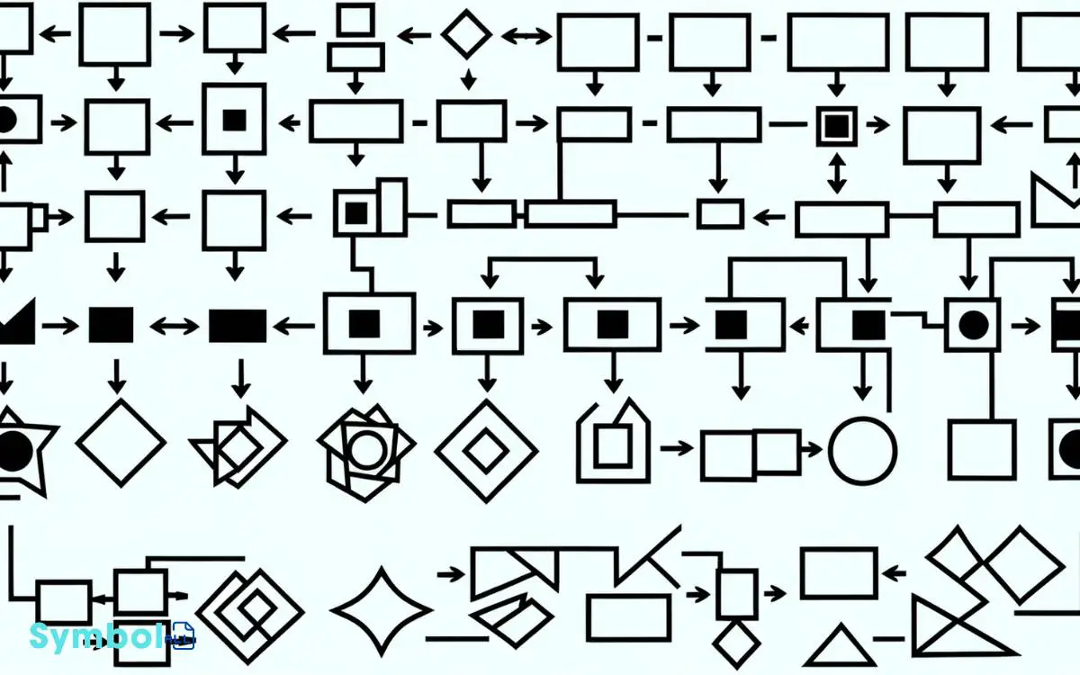
You’re stepping into the world of process engineering by dissecting the symbols in process flow diagrams. Rectangles indicate equipment, while circles mark inspection points, effortlessly simplifying complex operations.
Differentiating between pump and compressor icons is essential; they communicate fluid dynamics through varied symbols based on mechanism types. Valve and actuator symbols are your guide to functionality, offering a visual shorthand for their operations.
In heat exchangers, symbols illustrate heat transfer methods, optimizing system performance. Likewise, tanks and vessels are depicted by unique icons, essential for system analysis.
Understanding these symbols deepens your grasp on facility operations, paving the way for further exploration into the intricate language of process design.

Key Takeaways
14 Symbols of Process Flow Diagram Symbols
| Symbol | Name | Description |
|---|---|---|
| → | Arrow | Indicates the flow direction or the sequence of events in a process. |
| ⊡ | Process | A rectangular shape representing a process, function, or task within the flow. |
| ⊞ | Decision | A diamond shape representing a decision point, branching the flow into different paths based on yes/no questions. |
| O | Start/End | An oval shape representing the start or end of a process flow. |
| Δ | Data | A parallelogram shape representing input or output data in a process. |
| ⧈ | Document | A rectangle with a wavy bottom representing a document or report in the process. |
| ○ | Connector (In-page) | A small circle used to connect different parts of a process within the same page. |
| ⤓ | Connector (Off-page) | A pentagon shape representing a continuation of the process to another page. |
| ≡ | Preparation | A hexagon shape representing a preparation step in the process. |
| ⨁ | Manual Operation | A shape that looks like a trapezoid, representing a manual step that is not automated. |
| ⥣ | Merge | A triangle pointing upwards, indicating the merging of multiple process paths into one. |
| ⊠ | Delay | A D-shaped symbol representing a delay or wait in the process. |
| ⎚ | Display | A shape like a computer monitor, representing a step where information is displayed or presented. |
| ⧉ | Subroutine | A rectangle with double-struck vertical edges, indicating a set of instructions performed elsewhere in the process. |
Understanding Basic Symbols
To effectively interpret a process flow diagram, it’s crucial to familiarize yourself with the basic symbols that represent various components and operations within the system. You’ll come across lines and arrows indicating the flow direction of materials or products.
These lines are the diagram’s veins, showing how inputs navigate through the system to become outputs.
Rectangles or squares often symbolize equipment units or processes, serving as the nodes where transformation occurs.
Meanwhile, circles can denote inspection points where quality or compliance checks are conducted. Understanding these symbols allows you to grasp the operational essence of a facility quickly.
It’s not just about recognizing shapes; it’s about decoding the technical narrative they convey, ensuring you comprehend the process’s intricacies and efficiencies at a glance.
Pumps and Compressors Icons
In the domain of process flow diagrams, pumps and compressors are depicted through distinct icons that signify their role in moving and pressurizing fluids or gases within the system.
Pumps, essential for transporting liquids, are represented by symbols that vary based on their type and mechanism, such as centrifugal, diaphragm, or gear pumps.
Each icon is meticulously designed to convey the pump’s specific action, ensuring clear communication among engineers and technicians.
Compressors, on the other hand, are critical for increasing the pressure of gases. Their symbols differentiate between types like reciprocating, rotary, or centrifugal compressors.
Understanding these icons allows you to grasp the intricacies of the system’s fluid dynamics and pressure modulation. Mastery of these symbols is vital for effectively interpreting and designing process flow diagrams.
Valve and Actuator Symbols
As you transition into the domain of valve and actuator symbols, it’s essential to understand the range of valve symbol types, each denoting specific functionalities within process flow diagrams.
An overview of actuator symbols will arm you with the knowledge to identify how these devices interact with valves to control flow.
Understanding how to interpret valve positions guarantees you can accurately read and analyze system operations, providing a clear picture of process dynamics.
Valve Symbol Types
Understanding valve symbol types, including valve and actuator symbols, is essential for accurately interpreting process flow diagrams.
Each valve symbol you’ll encounter serves as a visual shorthand for the valve’s function, design, and how it’s operated within the system.
For instance, gate valves, which control flow via a movable gate, are represented by a distinct symbol differing from that of globe valves, which regulate flow using a spherical disc.
Additionally, check valves, ensuring unidirectional flow, possess their unique symbols to prevent confusion.
It’s vital to grasp these distinctions to comprehend system functionalities and maintenance needs accurately.
Delving into the specifics, the symbols not only depict the valve type but also hint at its method of actuation, though the latter is more explicitly detailed in actuator symbols.
Actuator Symbol Overview
Delving deeper into process flow diagram intricacies, it’s important to familiarize yourself with actuator symbols, as they directly influence valve operation and system control dynamics.
Actuators, represented by distinct symbols, are pivotal for the automated or manual control of valves.
These symbols depict the mechanism that actuates or moves the valve, essential for understanding how processes are controlled and manipulated.
In essence, actuator symbols delineate whether a valve is pneumatically, electrically, or hydraulically operated.
Each symbol variation provides insight into the valve’s control method, offering a clear indication of the actuation mechanism involved.
Grasping these symbols allows you to decode the operational aspects of process flow diagrams accurately, ensuring a thorough understanding of the system’s functionality and control strategy.
Interpreting Valve Positions
Building on your knowledge of actuator symbols, it’s essential to learn how to interpret valve positions through the integration of valve and actuator symbols for thorough control over process flow diagrams.
Understanding valve positions is vital for evaluating the flow path within a system. Each symbol isn’t just a representation; it’s a snapshot of the valve’s operational state.
For instance, a gate valve symbol in an open position suggests a clear path, whereas in a closed position, it indicates a blocked flow.
Analyzing these symbols, you’ll decipher whether a valve is normally open (NO) or normally closed (NC), which are default positions under no power or signal.
This knowledge enables you to predict system behavior, ensuring you’re equipped to troubleshoot or optimize the process efficiently.
Heat Exchangers and Coolers
Heat exchangers and coolers, essential components in process engineering, facilitate the efficient transfer of heat between two or more fluids without mixing them.
These devices play a pivotal role in optimizing energy use, enhancing system performance, and ensuring safety.
By understanding their symbols in process flow diagrams, you’re better equipped to grasp system functionalities and design intricacies.
Each symbol represents a different method of heat exchange, essential for process optimization.
Tanks and Vessels Representation
As you progress in analyzing process flow diagrams, it’s essential to grasp how tanks and vessels are represented.
The variety of tanks, from storage to pressure vessels, requires an understanding of specific symbols that indicate each type’s function and characteristics.
Interpreting these symbols accurately guarantees you can evaluate the system’s capacity and safety features effectively.
Types of Tanks
In process flow diagrams, tanks and vessels are represented by a variety of symbols, each denoting different types and functionalities essential for system operation.
You’ll encounter several distinct types, including storage tanks, which are typically depicted as cylindrical shapes for holding liquids or gases.
Pressure vessels, another common type, are designed to operate at pressures above atmospheric and are symbolized accordingly to highlight their critical features and operational capacity.
Reaction tanks, essential for processes that involve chemical reactions, are marked to indicate their specialized purpose and construction.
Each type’s representation is meticulously chosen to convey important information about capacity, material, and function, ensuring you can analyze and interpret system designs accurately and effectively.
Understanding these distinctions is vital for anyone involved in engineering or process design.
Symbol Interpretation
Why is it important to accurately interpret the symbols representing tanks and vessels in process flow diagrams?
In the domain of process engineering, every symbol carries weight, delineating specific types of tanks and vessels integral to the system’s operation.
A misinterpretation can lead to flawed design decisions, potentially compromising the efficiency, safety, and cost-effectiveness of the entire process.
For instance, a vertically striped rectangle symbolizes a fixed-roof tank, while a similar shape with a floating lid indicates a floating-roof tank, each serving distinct operational needs and handling different pressure levels.
Understanding these nuances guarantees you’re equipped to analyze and communicate the process intricacies effectively, facilitating precise engineering assessments and decisions.
It’s this level of detail that transforms a good engineer into a great one.
Piping and Connections
To effectively comprehend process flow diagrams, it’s crucial to familiarize yourself with the various symbols representing piping and connections, which serve as the arteries and junctions of any system design.
Piping is typically illustrated by solid lines, with their diameter and material specification often annotated alongside. These lines indicate the flow paths of materials or energy within the system.
Meanwhile, connections represent the interaction points between these paths and can vary greatly in complexity.
For instance, a simple connection might be depicted as a dot or a small circle, indicating a straightforward junction.
In contrast, more complex connections, such as valves or flanges, have unique symbols that provide insights into their function and how they regulate or facilitate the flow within the system.
Understanding these symbols allows you to grasp the nuances of system design and operation.
Instrumentation Identifiers
Exploring the domain of process flow diagrams, you’ll encounter an essential component known as instrumentation identifiers, which meticulously catalog and specify the various instruments and controls integral to system operations.
These identifiers are not merely arbitrary; they follow a structured notation to convey specific information about each instrument’s function, type, and location within the system. This precision aids in the seamless design, analysis, and maintenance of the process flow.
| Identifier | Description | Example |
|---|---|---|
| FIC | Flow Indicator Controller | Regulates flow rate |
| TE | Temperature Element | Measures temperature |
| PI | Pressure Indicator | Displays pressure level |
Understanding these symbols is crucial for anyone involved in engineering, process design, or operations, ensuring clear communication and operational efficiency across multidisciplinary teams.
Safety and Control Devices
Safety and control devices, integral to any process flow system, meticulously regulate operations to prevent accidents and guarantee efficiency.
You’ll encounter various symbols representing these devices in process flow diagrams (PFDs). Understanding these symbols is essential for analyzing and improving process safety and control.
Here’s a brief overview:
- Pressure Relief Valves (PRV): These symbols indicate devices designed to release excess pressure, preventing potential equipment failure or explosions.
- Temperature Controllers: Represented by a specific symbol, they maintain the temperature within predetermined limits, ensuring process stability and product quality.
- Flow Meters: Symbols for flow meters measure the rate of fluid flow, critical for controlling process conditions and ensuring operational safety.
Each symbol serves as a visual shorthand, enabling you to swiftly grasp the safety and control measures embedded within a system.
Conclusion
Just as a seasoned captain navigates the vast seas with a map marked by legends and symbols, you’ve now charted the complex waters of process flow diagrams.
From the powerful pumps, akin to the heartbeats of the system, to the intricate valves acting as gatekeepers, each icon serves an essential role.
With this knowledge, you’re equipped to decipher the technical labyrinth, ensuring safe passage through the industrial ocean, maintaining the vessel’s integrity with precision and skill.


