Manufacturing Process Flow Diagram Symbols: Explore!
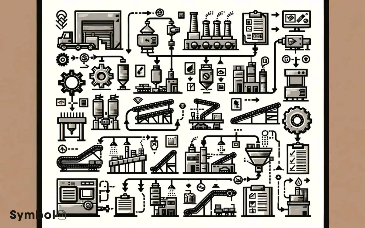
In manufacturing, process flow diagrams use symbols to represent equipment and operations, essential for understanding the sequence and identifying bottlenecks.
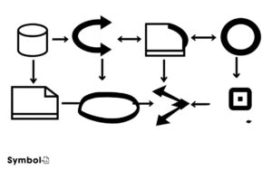
Common symbols include simple shapes for machinery, arrows for material flow direction, and unique icons for pumps, tanks, and valves. Solid lines depict main flows, while dashed lines show secondary paths.
Inspection and measurement symbols guarantee product quality, and delay icons help pinpoint inefficiencies. Mastering these symbols streamlines workflows and optimizes production.
By grasping the symbolic language, you’ll reveal the intricacies of manufacturing processes, paving the way for enhanced troubleshooting and efficiency improvements.
Key Takeaways
10 Symbols of Manufacturing Process Flow Diagram
| Symbol | Name | Description |
|---|---|---|
| ⬜️ | Process Flow Diagram Box | Represents a step in the process, typically a task or an operation. |
| ⭘ | Connector | Used to connect flow lines in a PFD when they break across pages. |
| → | Flow Line | Indicates the direction of process flow in the diagram. |
| Δ | Decision | Represents a branch in the process, where a decision is necessary. |
| O | Operation | An operation or action step in the process flow. |
| // | Delay | A delay or waiting period within the process flow. |
| ∇ | Input/Output | Represents materials entering or leaving the process. |
| ⚙️ | Equipment Symbol | Identifies a piece of process equipment, such as a pump or tank. |
| △ | Measurement | Used to denote a measurement point or monitoring of process variables. |
| ✱ | Inspection | Indicates an inspection point in the process. |
Understanding Basic Symbols
To effectively interpret a manufacturing process flow diagram, it’s vital to familiarize yourself with the basic symbols representing various equipment and operations.
These diagrams serve as the blueprint for the manufacturing process, outlining each step with distinct icons to guarantee clarity and efficiency.
You’ll encounter symbols that indicate processing activities, material movement, inspection points, and storage locations. Grasping these symbols allows you to understand the sequence of operations, identify potential bottlenecks, and optimize the production workflow.
It’s important to approach these diagrams with a keen eye, recognizing that each symbol has a specific meaning and function within the larger system.
By mastering the interpretation of these basic symbols, you’re equipped to explore deeper into the nuances of process flow diagrams, enhancing your ability to contribute to process improvement and operational excellence.
Common Process Flow Icons
As you move forward in creating manufacturing process flow diagrams, familiarizing yourself with common process flow icons becomes essential.
These symbols serve as the building blocks for diagramming and understanding complex manufacturing processes.
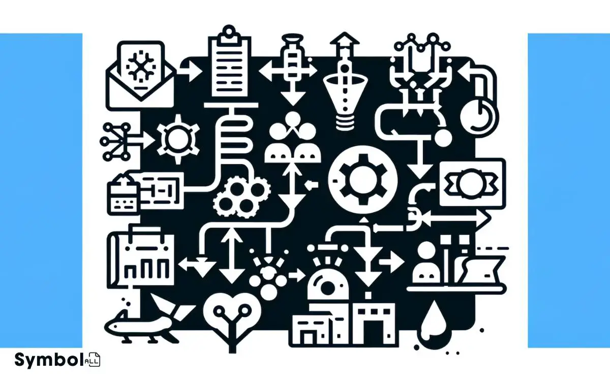
We’ll now explore key symbols and their meanings, ensuring you can accurately interpret and construct these essential diagrams.
Understanding Flowchart Symbols
Flowchart symbols serve as the essential language of process mapping, guiding you through manufacturing sequences with precision.
These icons represent various components of the process, from start to finish, enabling you to visualize operations, identify potential bottlenecks, and streamline workflows.
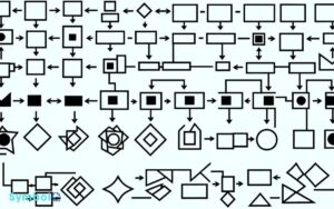
Each symbol has a specific shape, denoting a particular action or step in the process. For instance, rectangles often depict process steps or activities, while diamonds indicate decision points requiring a yes or no response.
Arrows connect the symbols, showing the flow direction and sequence of operations.
Understanding these symbols is vital, as it allows you to read and create flowcharts effectively, ensuring you’re equipped to communicate complex processes clearly and efficiently to your team or stakeholders.
Key Symbols Explained
Delving into the key symbols within manufacturing process flow diagrams, you’ll encounter specific icons that precisely represent various stages and decisions in the manufacturing workflow.
Rectangles denote process steps, where material or data undergoes a transformation. Diamonds highlight decision points, requiring a yes or no response to direct the flow.
Arrows guide the process direction, linking activities and decisions in a logical sequence. Parallelograms signify inputs and outputs, marking the introduction of resources or the export of finished goods.
Circles, often less common, act as connectors across different parts of the diagram, ensuring flow continuity across multiple pages or sections.
Understanding these symbols allows you to dissect and comprehend the complexities of manufacturing processes systematically.
Equipment Representation Symbols
In the domain of manufacturing process flow diagrams, you’ll come across different symbols representing equipment. It’s essential you comprehend these typical equipment symbols to interpret diagrams accurately.
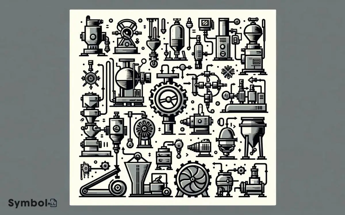
Next, we’ll lead you through a symbol interpretation guide to make sure you grasp their meanings and applications.
Common Equipment Symbols
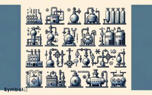
Understanding the common equipment symbols used in manufacturing process flow diagrams is essential for accurately interpreting and designing these schematics. You’ll encounter a variety of symbols, each representing a specific piece of equipment.
For instance, pumps are depicted with a series of circles and lines, indicating the direction of flow and the type of pump, whether it’s centrifugal or positive displacement.
Heat exchangers have their own unique symbol, often a pair of staggered rectangles, signifying the transfer of heat between two fluids.
Tanks are represented by simple rectangles or cylinders, sometimes with a line to indicate the liquid level. Valves, critical for controlling flow, are shown with symbols that detail their type and function, like gate, globe, or check.
Each symbol is a compact, standardized representation of equipment, designed for clarity and efficiency in communication.
Symbol Interpretation Guide
To accurately interpret manufacturing process flow diagrams, you’ll need a solid grasp of the equipment representation symbols detailed in this guide.
These symbols, standardized across the industry, serve as the building blocks for mapping out complex manufacturing processes.
For instance, a simple rectangle might represent a tank or vessel, while a circle could denote a pump.
Variations in these basic shapes, augmented with specific internal patterns or lines, further specify equipment types, such as heat exchangers or filters.
Understanding these nuances is vital; a dashed line might indicate a pneumatic or hydraulic connection, distinct from solid lines representing electrical connections.
Mastery of these symbols allows you to dissect and comprehend the operational intricacies depicted in flow diagrams, facilitating improved process analysis and troubleshooting.
Material Flow Indicators
You’ll encounter several symbols that represent material flow indicators, essential for interpreting manufacturing process flow diagrams accurately.
These symbols, designed for clarity and precision, guide you in understanding how materials move through various stages of the production process.
Arrows, for example, indicate the direction of material flow, showing how components travel from one process to the next.
Meanwhile, solid lines represent the main flow, and dashed lines suggest secondary or less significant movements.
Conveyor symbols depict material transport mechanisms, specifying whether the movement is continuous or batch.
Understanding these indicators is vital, as they provide insight into the efficiency, sequence, and methods of material handling within the manufacturing setup, ensuring you grasp the entire process flow without ambiguity.
Inspection and Measurement Icons
In manufacturing process flow diagrams, inspection and measurement icons play an important role in guaranteeing product quality and precision at every stage.
These symbols are vital for identifying points in the process where items are examined for compliance with technical specifications.
You’ll encounter various icons, each uniquely signifying the type of inspection or measurement activity to be conducted.
Understanding these icons ensures you’re equipped to interpret diagrams accurately, fostering a deeper comprehension of the manufacturing process.
Symbols for Storage and Delay
Understanding symbols for storage and delay is essential as they pinpoint where materials are held or processes are paused in a manufacturing flow diagram.
The typical symbol for storage is often depicted as a U-shaped open-top rectangle, signifying where raw materials, work-in-progress, or finished goods are stored. This visual cue helps you identify inventory points that may affect lead times or require optimization.
Conversely, delay symbols, represented by a D-shaped figure, indicate intentional pauses in the process flow. These pauses might be due to drying times, mandatory waiting periods, or scheduled maintenance.
Recognizing these symbols allows you to accurately assess process efficiency, identify bottlenecks, and plan for improvements.
Keep in mind, mastering these symbols enhances your ability to read and analyze manufacturing diagrams effectively.
Advanced Symbol Applications
Delving deeper, we explore advanced symbol applications that enhance your ability to decipher complex manufacturing processes. You’ll encounter symbols not just as standalone entities but as components of intricate systems.
Their arrangement and interconnectivity on diagrams provide a narrative of operational dynamics, essential for troubleshooting and optimization.
| Symbol | Interpretation | Emotional Impact |
|---|---|---|
| ⚙️ | Machinery Operation | Evokes reliability and precision |
| � | Process Loop | Suggests continuity and cycle |
| � | Decision Point | Induces moments of critical thinking |
Understanding these symbols in detail allows you to visualize the unseen, making the invisible processes tangible.
Each symbol is a key, revealing parts of the process flow that are critical for efficiency, safety, and innovation.
This proficiency transforms diagrams from mere representations to dynamic stories of production and potential.
Conclusion
In wrapping up, imagine the manufacturing process flow diagram symbols as the DNA of industrial blueprints, intricate yet essential.
You’ve now got the toolkit—from basic symbols to advanced applications—enabling you to decode and design with precision.
Like a cartographer mapping uncharted territories, you can chart the course of production with clarity.
Remember, each icon, from equipment representations to material flow indicators, plays an important role, ensuring your manufacturing narrative is both efficient and error-free.

