Flow Control Valve Pneumatic Symbol: Air Flow Rate!
To understand the flow control valve pneumatic symbol, you need to grasp its components. These symbols provide precise control over air flow rate, essential for your system’s efficiency and performance.
Typically, they feature lines for air pathways, arrows indicating flow direction, and variable elements for adjustability. Look for rectangles or diamonds representing valve bodies, a hallmark of the symbol’s functionality.
Choosing the right symbol hinges on analyzing pressure requirements, flow rate, and medium. Ensuring compatibility with your operating environment is important.
Mastering these symbols will greatly enhance your pneumatic system’s efficiency, subtly pushing you closer to optimizing your operations.

Key Takeaways
Understanding Pneumatic Symbols
To understand the core of a pneumatic system’s operation, it’s important to grasp its symbols, which serve as the language of its design and functionality.
These symbols aren’t simply abstract designs; they’re precise representations of components and their interactions within the system.
Each symbol encapsulates a wealth of information about the type of component it represents, its function, and how it integrates with other parts of the system.
By learning these symbols, you’re effectively deciphering a complex language that dictates how compressed air moves and is controlled within the system.
Mastery of this symbolic language enables you to analyze, troubleshoot, and design pneumatic systems with a higher degree of accuracy and efficiency. It’s a fundamental skill for anyone looking to explore further into the world of pneumatics.
The Basics of Flow Control Valves
Understanding flow control valves is essential, as they precisely regulate the rate of air flow in a pneumatic system. These valves are critical for maintaining the desired performance and efficiency of your equipment.
You’ll find them indispensable in applications where you need to control the speed of actuators or to stabilize the pressure and flow rate in different parts of the system.
Here are key points to remember about flow control valves:
- They can be manually or automatically adjusted.
- Offer fine control over air flow rate.
- Essential for optimizing pneumatic system efficiency.
- Differ in design based on application needs.
Identifying the Symbol Components
Before diving into the specifics, it’s essential you’re familiar with the symbol components of flow control valves in pneumatic systems. The symbols serve as the visual language conveying how these valves regulate air flow.
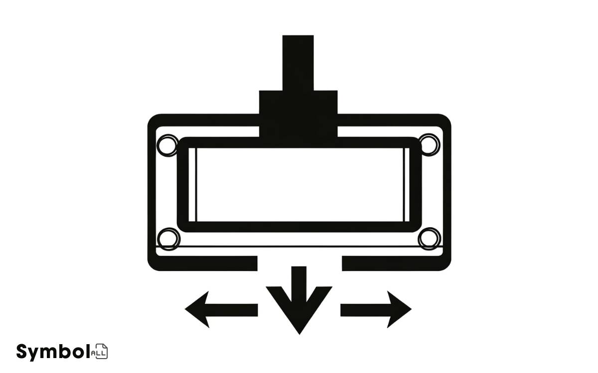
At its core, a flow control valve symbol includes lines representing pathways for air movement, arrows indicating the direction of flow, and often a variable element suggesting adjustability.
You’ll notice rectangles or diamonds, denoting the valve body, with lines intersecting or branching, which reflect ports or positions. The presence of an arrow across these shapes signifies adjustability in flow rate.
Understanding these components allows you to grasp how the valve functions, laying the groundwork for deeper insights into their operation and integration within pneumatic circuits.
Significance in Pneumatic Systems
Understanding the pneumatic symbol for flow control valves is essential for enhancing system efficiency and reducing maintenance requirements in your pneumatic systems.
Accurately interpreting these symbols allows you to optimize airflow and pressure control, which directly impacts system performance.
This knowledge not only streamlines operations but also greatly lowers the frequency and intensity of maintenance needed, ensuring a more reliable system operation.
System Efficiency Enhancement
In optimizing pneumatic systems, enhancing system efficiency directly impacts energy consumption and operational performance.
You’ll find that improved efficiency not only reduces costs but also extends the lifespan of your system components.
Consider these key factors:
- Precise Flow Control: Optimizing the flow rate through valves guarantees that energy isn’t wasted, leading to significant savings.
- Leakage Reduction: A well-designed system minimizes leaks, which are a common source of inefficiency and lost energy.
- Best Pressure Settings: Adjusting the system to operate at the lowest possible pressure for the application reduces energy consumption.
- Temperature Regulation: Maintaining best temperatures reduces the risk of component failure and inefficiency.
Maintenance Requirements Reduction
Reducing maintenance requirements in pneumatic systems greatly enhances operational reliability and cost efficiency.
By optimizing the design of flow control valves and incorporating advanced materials, you can notably reduce wear and tear, extending the system’s lifespan.
It’s important to understand that minimizing maintenance doesn’t just cut down on direct costs related to repairs and replacements; it also reduces downtime, ensuring that your system operates at peak efficiency for longer periods.
Implementing predictive maintenance strategies, such as regular monitoring and analysis of pneumatic symbols and components, allows you to identify potential issues before they escalate.
This proactive approach not only saves you time and money but also maintains the system’s integrity and performance.
Interpreting Schematics
You must first grasp the basics of reading schematic symbols to accurately interpret pneumatic system diagrams.
Understanding symbol complexity levels is important, as it allows you to decode the functionality and integration of components.
We’ll also clarify common symbols, enhancing your ability to analyze and troubleshoot system designs efficiently.
Reading Schematic Symbols
Deciphering schematic symbols is indispensable for understanding how flow control valves operate within pneumatic systems.
To effectively read these schematics, you’ll need to familiarize yourself with various symbols and what they represent.
Here’s a breakdown to guide you:
- Lines and Arrows: Indicate the direction of airflow and connections between components.
- Squares and Rectangles: Often represent the valves themselves, including their state (open or closed).
- Triangles: Symbolize the directionality of control elements, such as actuators.
- Dots and Intersections: Show where lines connect or cross without connection, essential for tracing flow paths.
Understanding these symbols allows you to analyze pneumatic circuits accurately, ensuring you can troubleshoot or design systems effectively.
Symbol Complexity Levels
As we delve further into interpreting schematics, it’s vital to understand that symbols vary in complexity, directly impacting your ability to analyze and design pneumatic systems.
This variety isn’t random but reflects the function and operation of the component it represents. Simple symbols might denote basic parts like pipes or connectors, requiring minimal interpretation.
In contrast, more intricate symbols represent valves, actuators, or compressors, incorporating additional details to depict function, direction of flow, and control mechanisms.
Grasping the hierarchy of symbol complexity is important for accurate schematic analysis. It enables you to dissect a system’s layout methodically, ensuring that you don’t overlook critical details or misinterpret the functionality of sophisticated components.
This knowledge forms the foundation of effective pneumatic system design and troubleshooting.
Common Symbols Explained
Building on the understanding of symbol complexity, let’s explore common symbols in pneumatic schematics, focusing on their interpretation and significance.
Recognizing these symbols enhances your ability to navigate and understand pneumatic diagrams efficiently.
Here’s a concise breakdown:
- Single-acting cylinder: A rectangle with one square edge indicates a single-acting cylinder, where air pressure moves the piston in one direction, and a spring returns it.
- Double-acting cylinder: Two square edges on a rectangle denote a double-acting cylinder, allowing for air-controlled movement in both directions.
- Directional control valves: Illustrated by square boxes with arrows, these symbols vary by the number of positions and ports, controlling the flow path.
- Pressure relief valves: A valve symbol with an arrow across its corner represents a pressure relief valve, important for maintaining desired pressure levels.
Tips for Effective Usage
To guarantee peak performance, it’s essential that you choose the right flow control valve pneumatic symbol for your application. Understand that each symbol represents specific functionalities and limitations.
It’s vital to analyze your system’s pressure requirements, flow rate, and the medium being controlled. Opt for symbols indicating adjustable flow rates if you’re dealing with variable process conditions.
Make sure compatibility with the pneumatic system’s operating environment to prevent premature failure. Regularly review technical specifications and consult with manufacturers to select the most suitable symbol, considering future scalability and maintenance needs.
Conclusion
In mastering the intricacies of pneumatic symbols, you’ve bridged the gap between confusion and clarity. By dissecting the components of flow control valve symbols, you’ve revealed a critical layer of understanding in pneumatic systems.
Remember, interpreting schematics isn’t just about recognizing symbols; it’s about envisioning the air’s journey through the system. As you apply these insights, you’re not just following diagrams; you’re choreographing the breath of machines.
Your ability to wield these symbols with precision turns abstract diagrams into the lifelines of automation.


