Flow Chart Symbols in Programming: A Guide!
In programming, you’ll use specific flow chart symbols to map out algorithms and logical sequences. The start symbol marks your entry point, setting up structured operations.
Mastering these symbols is essential for understanding programming logic. Grasping their meanings opens up a clearer understanding of algorithms.
Key Takeaways
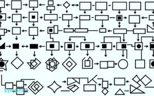
Flow Chart Symbols and Their Meanings in Programming
| Symbol | Name | Purpose | Shape Description |
|---|---|---|---|
| ➔ | Arrow | Indicates the flow of control | A line with an arrowhead showing direction |
| □ | Process | Represents an instruction or action | A rectangle |
| ◯ | Start/End | Denotes the beginning or end of a process | An oval or rounded (terminal) shape |
| △ | Decision | Used for decision-making with yes/no or true/false | A diamond |
| ◇ | Input/Output | Signifies the point of data entry or display | A parallelogram |
| ⫱ | Predefined Process | Indicates a set of operations that are defined elsewhere | A rectangle with double-struck vertical edges |
| ≡ | Data (or Database) | Represents data storage or databases | A cylinder or an open rectangle |
| // | Parallel Mode | Shows processes that can occur simultaneously | Two long vertical lines with horizontal lines connecting them |
| ⟲ | Loop Limit | Marks the beginning or end of a loop | A rectangle with the bottom corner folded over, or a backward ‘P’ shape |
Understanding the Start Symbol
The start symbol, often depicted as an oval or circle, marks the initial entry point of a program in flowchart diagrams, setting the stage for a structured sequence of operations.
You’re probably aware that programming involves complex processes, and visualizing these through flowcharts can greatly ease understanding. The start symbol serves a critical role here; it’s your cue that what follows is a series of actions intended to fulfill a specific task.
It’s not merely an indicator of beginning but a signpost guiding you through the logical steps programmed to achieve an outcome. By recognizing this symbol, you’re equipped to trace the flow of operations accurately, discerning the program’s architecture with clarity and precision.
This foundational understanding is essential, especially when dissecting or constructing flowcharts for programming purposes.
The Role of the End Symbol
As you move from the start symbol, it’s vital to grasp the end symbol‘s importance in programming flowcharts. It signifies not only the conclusion of the process but also indicates the termination of program execution.
Understanding the functions associated with this symbol is necessary for accurately mapping out a program’s flow and ensuring a clear, error-free conclusion.
Signifying Program Termination
In programming flowcharts, you’ll often encounter the end symbol, a critical component that unequivocally indicates the termination of a program.
This symbol is more than just a formality; it’s a clear, visual cue that signals the end of the program’s execution path. It’s essential for understanding the flow and structure of the program, ensuring that you can accurately trace the sequence of operations from start to finish.
The end symbol serves as a full stop, telling you that no further actions occur within the program’s logic. Its presence is crucial for both the programmer, who designs and debugs the software, and the reader, who may be analyzing or learning from the code.
Without it, determining the program’s boundary becomes considerably more challenging, potentially leading to confusion or misinterpretation of the program’s intended functionality.
Understanding End Functions
Delving into the importance of end symbols, it’s essential to understand how they serve as the definitive point signaling a program’s conclusion. These symbols aren’t just decorative; they’re pivotal for delineating the boundary of your program’s logic flow.
Essentially, they tell you, ‘This is where the actions and processes stop.’ Without this clear termination point, it’d be difficult to discern where to end the execution or identify the scope of your program’s operation.
Furthermore, in a complex flowchart, the end symbol guarantees that every thread of logic is accounted for, preventing loose ends that can lead to errors or unintended behavior.
It’s the full stop in your programming sentence, ensuring that your program’s execution sequence is neatly concluded, leaving no ambiguity for the machine or the next developer revisiting your code.
Decision Points Explained
Decision points function as critical junctures in flow charts, directing the flow based on conditional logic. In programming, these points are where decisions are made, typically represented by a diamond shape.
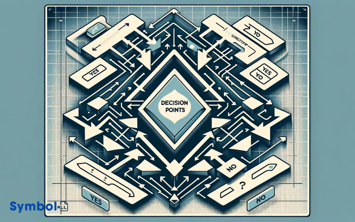
You’ll encounter them when a process involves a yes/no or true/false question, leading to different outcomes based on the answer. Understanding how to effectively use decision points is essential for creating efficient and clear flow charts.
They require you to ask a specific question that can be answered in two ways. Depending on the response, the flow of the program will branch into one of two paths.
This bifurcation is what allows complex logic to be simplified into manageable parts within a program’s structure. Hence, mastering decision points is vital for any programmer aiming to design logical and functional flow charts.
Process Operations Demystified
Understanding process operations is vital as they represent the steps your program takes to carry out tasks and achieve its goals. In programming flowcharts, these operations are depicted by rectangles, guiding you through the execution sequence.

Each rectangle encapsulates a specific action or a set of actions, making complex procedures manageable by breaking them down into manageable parts.
Analyzing these operations requires a clear understanding of the task at hand and the logical sequence needed to accomplish it.
You’ll often find arithmetic calculations, data manipulation, and various algorithmic processing within these blocks.
By dissecting each process operation, you guarantee your program’s logic is both efficient and effective, laying a solid foundation for troubleshooting and optimization.
Input and Output Operations
In the domain of programming flowcharts, input and output operations serve as essential junctions where your program interacts with the external world, capturing data and presenting results.
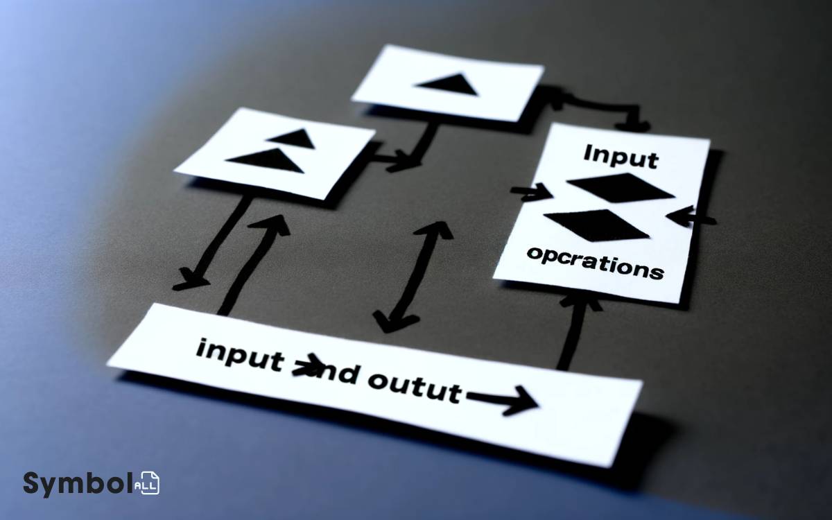
These operations are symbolized uniquely, guiding programmers in structuring and understanding how data flows through a system.
| Symbol | Emotion Evoked |
|---|---|
| Parallelogram | Anticipation of receiving or displaying information. |
| Arrow | Direction, movement, a journey through the process. |
| Oval | Completion, the beginning or end of a cycle. |
Understanding these symbols allows you to grasp the essence of data interaction within your program. The parallelogram, for instance, doesn’t just represent data entry or display; it signifies the pivotal point of human-computer interaction, evoking anticipation and satisfaction.
As you chart these operations, you’re not merely drafting a program’s blueprint; you’re mapping the journey of data, from input to transformative process, and finally to output, where it meets the world.
Symbolizing Subroutines
As you move from comprehending input and output operations, it’s vital to understand how subroutines are symbolized within flow charts.
Subroutine representation icons provide a visual shorthand for these modular and reusable code blocks, offering clarity in intricate programming structures.
Linking subroutines visually guarantees a coherent flow, making the overall program simpler to follow and debug.
Subroutine Representation Icons
To effectively utilize subroutines in your programming flowcharts, it’s important to recognize the specific symbols that represent these modular code blocks. These icons simplify the understanding of the flowchart’s logic, enabling you to design and debug efficiently.
Below is a table highlighting common symbols:
| Symbol | Description |
|---|---|
|  | Represents a process or subroutine call. Often labeled with the subroutine name. |
|  | Indicates the start or end point of a subroutine within the larger program flow. |
|  | Suggests input or output operations related to subroutines, like parameters passing or return values. |
|  | Marks a connector or jump within the subroutine, helping to manage complex subroutine logic. |
Understanding these icons is foundational to effectively mapping out subroutine logic and interactions within your flowcharts.
Linking Subroutines Visually
Understanding how to visually connect subroutines within your programming flowcharts is essential for depicting their relationships and interactions clearly and effectively.
When you’re mapping out your software’s architecture, the way you symbolize these connections can make or break the comprehensibility of your design.
Typically, you’ll use lines or arrows to link subroutine symbols, indicating the flow of control or data. It’s vital that these connectors are used consistently throughout your flowchart to avoid confusion.
Moreover, adding labels or brief descriptions near these linkages can provide additional clarity, especially when the relationship isn’t straightforward. Remember, the goal is to make the flowchart intuitive.
By ensuring that every connection between subroutines is visually represented with precision, you’re not just making your flowchart easier to follow; you’re also laying a solid foundation for effective communication within your development team.
Data Preparation Indicators
Why should you pay attention to data preparation indicators in flow charts? These symbols are essential for understanding how data is manipulated before it’s processed or analyzed.
They offer a visual representation of the steps involved in preparing data, such as sorting, merging, or formatting.
By analyzing these indicators, you’re equipped to foresee potential issues, optimize data handling processes, and guarantee the accuracy of your programming logic.
Data preparation is often the foundation upon which the rest of the flow chart is built. Without a clear understanding of this stage, the subsequent steps might be misinterpreted or improperly executed.
Recognizing and applying these indicators accurately in your flow charts not only enhances clarity but also improves the efficiency and effectiveness of your programming strategy.
Flow Lines and Arrows
You’ll find that flow lines and arrows are essential in mapping out the direction of operations within a flowchart.
The orientation and shape of arrow tips, particularly, play a crucial role in illustrating the sequence of actions.
Directional Flow Indicators
Directional flow indicators, such as flow lines and arrows, are essential for guiding the reader through a program’s logic in flow charts.
Here’s what you need to know about them:
- Flow lines connect different elements within the chart, visually representing the sequence of operations.
- Arrows indicate the direction of the flow, pointing from one step to the next.
- Consistency in using these indicators prevents confusion, ensuring that the flow remains intuitive and straightforward.
- Crossing lines should be minimized; if unavoidable, use bridge symbols or arcs to maintain clarity without altering the directional flow.
Understanding these elements allows you to dissect complex logic into manageable, sequential steps.
Arrow Tips Significance
Having explored the role of flow lines and arrows in guiding the logic of flow charts, let’s now focus on the significance of arrow tips in these visual aids.
Arrow tips aren’t mere decorations; they’re essential for understanding the directionality and progression of steps within a flow chart.
Their design and orientation can subtly influence the readability and interpretation of the chart’s logic.
| Arrow Tip Shape | Significance |
|---|---|
| Simple Arrow | Indicates a single direction of flow. |
| Notched Arrow | Signifies a conditional or decision point. |
| Hollow Arrow | Suggests a return to a previous step or loop. |
| Dotted Arrow | Denotes a reference or call to another chart. |
| Double Line | Implies parallel processes or operations. |
This table showcases how varied arrow tips can denote specific actions or steps, enabling you to decipher the flow chart’s logic more effectively.
Connector Symbols in Detail
Let’s explore connector symbols, essential components that enable the flow of logic in programming diagrams. These symbols act as bridges within the flowchart, ensuring that the sequence of actions is maintained without visual clutter.

Understanding them enhances your ability to decode and construct complex algorithms effectively.
- Circles: Often used to represent a jump in the flowchart, allowing continuation from one part to another without drawing long lines.
- Arrows: Direct the reader’s attention, indicating the direction of the flow from one connector to another.
- Letters or Numbers: Each connector is uniquely identified, enabling a clear link between different sections of the flowchart.
- Plus Sign (+): Sometimes used to denote a merge in the process flow, highlighting where multiple paths converge into a single point.
Loops and Iterations Visualized
In programming flowcharts, loops and iterations are symbolized by shapes that visually represent the cyclical nature of these processes, illustrating how certain blocks of code are executed multiple times based on specific conditions.
Typically, these are depicted using rectangles or parallelograms, connected by arrows that loop back to an earlier point in the diagram.
This looping back signifies the repetition of tasks until a certain condition is met, such as reaching the end of a list or satisfying a particular logical condition.
You’ll often encounter two main types: ‘for’ loops and ‘while’ loops, each having its essential symbol or notation.
Understanding these symbols is important as they provide a clear, structured way to visualize the control flow, making it easier to grasp the logic behind the code’s operation and predict its execution path.
Conclusion
In wrapping up, you’ve now peered into the core of programming’s visual language through flowchart symbols, unraveling the mystery behind each shape and line.
These symbols aren’t just random; they’re the backbone of logical thinking in coding, transforming abstract ideas into tangible steps.
By understanding the intricacies of each, from the initiating spark of the Start symbol to the conclusive certainty of the End, you’ve equipped yourself with the tools to dissect and construct complex processes.
This exploration confirms the theory: mastering these symbols is akin to learning a new language, opening doors to clearer communication and problem-solving in the programming world.


