How to Identify the Electrical Symbol for a Transformer
The electrical symbol for a transformer often consists of two inductively linked coils depicted by parallel lines or concentric circles, representing primary and secondary windings. Variations in the symbol include configurations for single-phase and three-phase transformers, autotransformers, and specific designs indicating voltage adjustment taps.
Additionally, different core types such as laminated, toroidal, and air cores are symbolically represented to convey unique properties. These symbols follow international standards for clarity and consistency in electrical schematics.
To guarantee thorough comprehension and effective schematic interpretation, understanding these variations and their specific representations is essential.

Key Takeaways
- Basic transformer symbols consist of parallel lines or concentric circles representing primary and secondary windings.
- The symbol may include taps for voltage adjustments, indicating autotransformers or other variations.
- Core configurations like laminated, toroidal, and air core are represented by specific standardized symbols.
- Step-up and step-down transformers are depicted by symbols showing expanding or contracting lines for windings.
- Standard symbols include a rectangle with parallel lines for the magnetic core and circles or dots for windings.
Basic Transformer Symbol
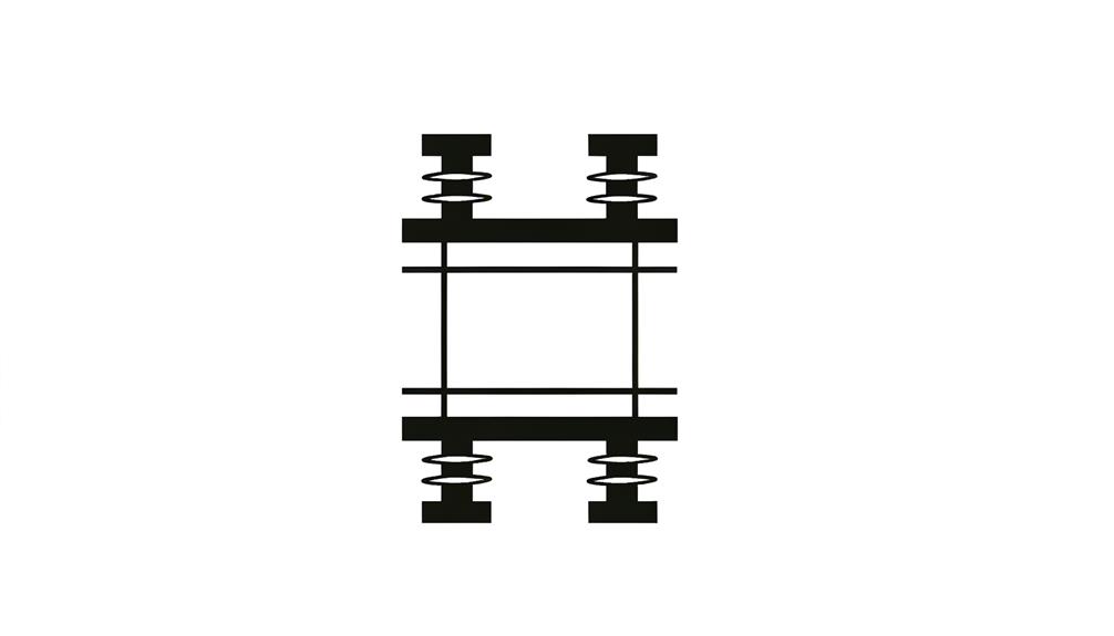
The basic transformer symbol in electrical diagrams typically consists of two inductively coupled coils, represented by parallel lines or concentric circles, which indicate the primary and secondary windings.
The parallel lines version is more common in simplified circuit diagrams, while the concentric circles are often used in more detailed technical schematics. Each set of lines or circles is connected to the circuit, denoting the input (primary) and output (secondary) sides of the transformer.
The symbol's primary purpose is to illustrate the transfer of electrical energy via electromagnetic induction. It provides an intuitive understanding of the transformer's function, ensuring accurate interpretation and implementation in electrical systems.
Fundamental to electrical engineering, this symbol simplifies complex concepts for practical application.
Variations in Symbol Design
Variations in transformer symbol design arise from the need to represent different types of transformers and their specific functionalities in electrical schematics. These adaptations make sure that each type of transformer is accurately depicted for its intended application.
Key variations include:
- Single-Phase vs. Three-Phase Transformers: Single-phase transformers are represented with two coils, while three-phase transformers are depicted with three coils.
- Taps: Symbols may include taps to indicate voltage adjustment points on the windings.
- Autotransformers: These are shown with a single continuous winding, distinguishing them from standard transformers.
- Isolating Transformers: These are often marked with a separation line between primary and secondary windings to denote electrical isolation.
These distinctions aid in the precise interpretation of electrical designs and schematics.
Core Types and Symbols
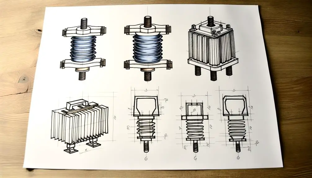
Core types in transformers significantly impact performance and symbol representation. The three primary core configurations are laminated core, toroidal core, and air core. Each core type has a specific standardized symbol that communicates its distinct physical and electrical attributes. Mastery of these symbols is crucial for precise schematic interpretation and successful transformer design.
Understanding the core types in transformers is vital for comprehending how they influence performance and symbol representation. The laminated core, toroidal core, and air core are the key configurations that play a significant role in the functioning of transformers. Each core type is associated with a standardized symbol that reflects its unique physical and electrical properties. Proficiency in deciphering these symbols is essential for accurately interpreting schematics and designing transformers effectively.
Core Configuration Variations
Transformer core configurations impact the performance and efficiency of the transformer. Various types such as shell-type, core-type, and toroidal are represented by distinct electrical symbols. These variations influence electromagnetic flux distribution, losses, and overall effectiveness.
The core configurations can be categorized as follows:
- Core-Type: Characterized by windings encircling the core limbs, it provides a straightforward design for lower loss.
- Shell-Type: Features windings enclosed by the core, offering enhanced magnetic shielding and reduced leakage flux.
- Toroidal: A doughnut-shaped core with minimal leakage inductance and superior efficiency.
- C-Core: Comprises two C-shaped cores that simplify assembly and improve magnetic properties.
Each configuration's symbol assists in accurate representation and understanding of the transformer's design and functionality.
Standard Symbol Representation
Standardized electrical symbols provide a clear and precise method for depicting various transformer core types in engineering schematics. Symbols such as the rectangle with two parallel lines indicate a magnetic core, while circles or dots represent the windings.
Core types like shell-type, represented by a rectangle with a central line, and core-type, depicted by a rectangle without a central line, are standard. Iron-core transformers are illustrated with a dashed line, signifying the presence of magnetic material. Air-core transformers, devoid of such material, use solid lines only.
These symbols adhere to international standards such as IEC 60617 and IEEE 315, enabling engineers to communicate complex designs efficiently and uniformly across various platforms and disciplines.
Single-Phase Transformer Symbol
In electrical schematics, the symbol for a single-phase transformer typically consists of two parallel lines representing the core, with windings depicted on either side to denote the primary and secondary coils. This straightforward representation captures the essential function of a single-phase transformer in altering voltage levels between circuits.
Key features include:
- Core Lines: Two parallel lines depict the magnetic core, essential for flux linkage.
- Windings: Curved lines or coils on either side of the core represent the primary and secondary windings.
- Dots: Often, dots are placed next to the windings to indicate phase orientation.
- Voltage Indication: Labels near the windings specify the input and output voltages, ensuring clarity in circuit design.
This symbol simplifies the visualization of transformer operations in single-phase applications.
Three-Phase Transformer Symbol
While single-phase transformers are common in residential applications, the symbol for a three-phase transformer is more complex and involves a combination of three interconnected single-phase transformer symbols. This configuration typically represents the three windings: primary, secondary, and tertiary.
Each winding is denoted by a pair of lines, and the interconnections are often displayed in a delta (Δ) or wye (Y) arrangement, indicating the phase relationships. The primary winding connections are usually depicted on one side, with secondary windings on the opposite. Additionally, the symbols may include dots to indicate winding polarity, ensuring correct phase alignment.
Understanding these symbols is essential for interpreting electrical schematics in industrial and commercial power distribution systems.
Autotransformer Symbol
The autotransformer symbol distinctly represents its single winding structure, which functions as both the primary and secondary winding.
This unique configuration is typically depicted with a single coil and a tap, demonstrating its ability to adjust voltage levels within the same winding.
Detailed representation of the core and winding configurations are essential for accurately conveying the operational principles and electrical connections of autotransformers.
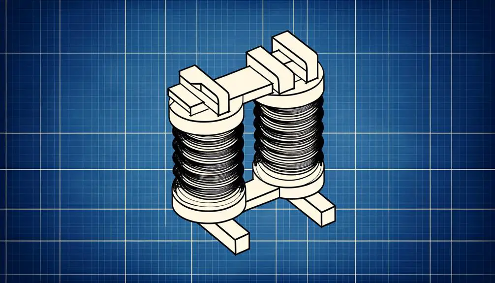
Autotransformer Core Representation
Autotransformers are represented by a distinct electrical symbol that differentiates them from conventional transformers, typically featuring a single winding that acts as both the primary and secondary coil. This unique representation adheres to specific conventions to guarantee clear communication in electrical schematics.
Key features include:
- Single Winding: Unlike traditional transformers, the symbol shows a single continuous winding.
- Tap Points: Indicated by taps along the winding, representing different voltage levels.
- Core Representation: Often depicted with parallel lines to illustrate the magnetic core, essential for operational efficiency.
- Connection Notations: Clear labeling of input and output connections, often with distinct markings to show the shared winding nature.
These elements collectively guarantee precise and unambiguous representation of autotransformers in technical diagrams.
Winding Configuration Details
Comprehending the winding configuration details of an autotransformer symbol is crucial for accurately interpreting its function and integration within electrical circuits.
An autotransformer features a single winding that serves as both the primary and secondary winding, with a tap point to provide a variable voltage output. This configuration is typically represented by a continuous line in the schematic, indicating a shared winding. The tap point is usually marked along the winding, indicating the connection point for the output voltage.
Additionally, the ratio of the winding turns between the input and the tap point determines the voltage transformation ratio. Recognizing these symbols guarantees proper identification and application in circuit designs, facilitating efficient energy transfer and voltage regulation.
Step-Up Vs. Step-Down Symbols
Differentiating between step-up and step-down transformer symbols necessitates an understanding of their core functionalities and distinct graphical representations. Step-up transformers increase voltage from primary to secondary windings, while step-down transformers decrease it.
Here are the key differences in their symbols:
- Primary Winding: Both types feature primary windings, but in step-up transformers, the primary winding is depicted with fewer turns compared to the secondary.
- Secondary Winding: In contrast, step-down transformers show a primary winding with more turns than the secondary.
- Voltage Indicators: Step-up symbols may include voltage indicators specifying an increase, whereas step-down symbols indicate a decrease.
- Graphical Representation: The graphical depiction uses parallel lines for windings, with the step-up showing expanding lines and the step-down showing contracting lines.
Symbol Usage in Diagrams
In electrical schematics, transformer symbols are necessary for accurately representing the function and configuration of the transformers within the circuit. These symbols provide visual shorthand for complex electrical concepts, facilitating a clear understanding of the circuit's design.
Different transformer configurations, such as step-up or step-down, are depicted using specific symbols to denote their primary and secondary windings. Additionally, symbols may include notations for core type (iron or air) and tap positions.
The correct usage of these symbols ensures that anyone reviewing the schematic can quickly grasp the intended electrical behavior and connections. Precision in symbol usage is vital for avoiding misinterpretations that could lead to design flaws or operational failures.
Importance in Electrical Schematics
The precise depiction of transformer symbols in electrical schematics is vital for guaranteeing the correct interpretation and functionality of the circuit design. This accuracy is crucial for several reasons:
- Component Identification: Accurate symbols aid in identifying the transformer type and its specifications, ensuring compatibility with other circuit elements.
- Fault Diagnosis: Clear schematic representations assist in troubleshooting by enabling engineers to pinpoint issues efficiently.
- Safety Compliance: Proper symbol usage ensures adherence to industry standards, reducing potential hazards and guaranteeing regulatory compliance.
- Documentation Consistency: Standardized symbols contribute to uniform documentation, facilitating communication among engineers and technicians.
These factors highlight the significance of meticulous symbol representation in electrical schematics, promoting effective design, maintenance, and operation of electrical systems.
Conclusion
In electrical schematics, the precise depiction of transformer symbols is vital for the correct interpretation and implementation of circuit designs.
Especially, the global transformer market is forecasted to reach $98.3 billion by 2026, emphasizing the growing dependence on these components in different applications.
Understanding the intricacies of transformer symbols, such as core types, phase configurations, and functional differences, guarantees efficient communication among engineers and boosts the dependability of electrical systems.