Electrical Symbol for a Switch: What Is It?
In electrical schematics, switch symbols graphically represent the operational state and function of switches. The basic symbol typically depicts a gap in a line, illustrating an open or closed circuit.
Symbols vary by switch type, including single-pole (SPST), double-pole (DPST), and momentary switches like push-buttons. Each symbol ensures accurate communication of switch roles and enhances diagram clarity.
For instance, a single-pole switch is shown as a line intersecting a break, while double-pole switches control two circuits simultaneously. This standardized approach is crucial for engineers designing and interpreting electric systems.
Continuing forward, you'll discover more details on specific switch applications.
Key Takeaways
- The basic switch symbol represents an open or closed circuit crucial for electrical schematics.
- Single-Pole switches control a single circuit and are common in residential and commercial settings.
- Double-Pole switches manage two separate circuits, enhancing system reliability and safety.
- Momentary switch symbols include normally open (NO) and normally closed (NC) configurations for precise control in various applications.
- Switch symbols ensure standardized communication in electrical diagrams, essential for accurate interpretation and construction.
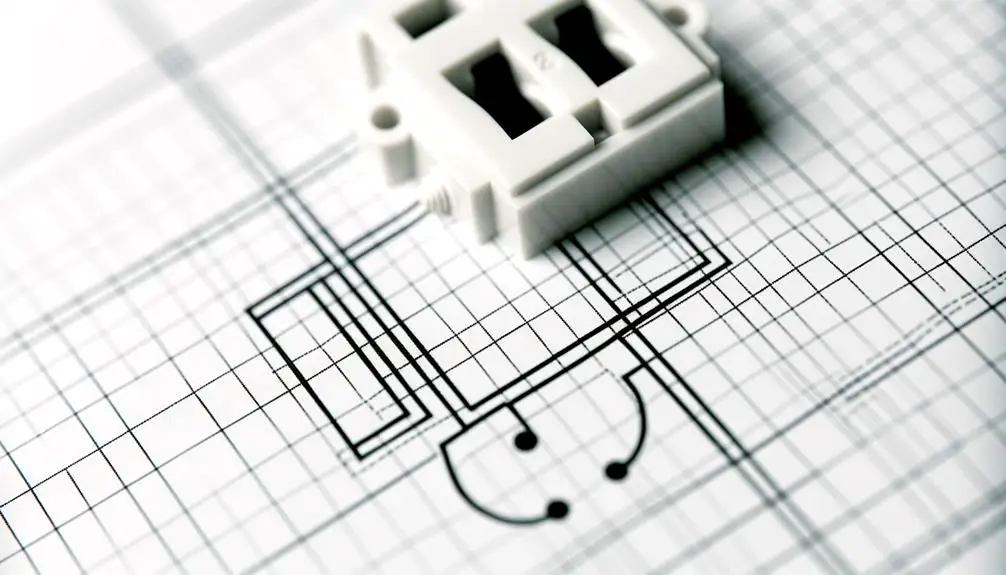
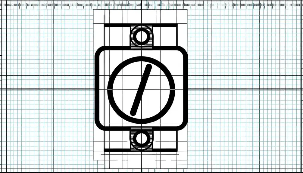
Basic Switch Symbol
The basic switch symbol, frequently encountered in electrical schematics, typically consists of a simple break in a line to indicate an open or closed circuit. This rudimentary representation is essential for conveying the binary operational states of a switch: either interrupting or completing the electrical pathway. Technicians and engineers rely on this symbol to diagnose and design circuit diagrams with clarity and accuracy.
The symbol's straightforwardness guarantees it can be universally understood, minimizing the risk of misinterpretation. In more complex schematics, the basic switch symbol serves as a foundational element upon which additional specifications and functionalities can be layered. This makes it indispensable for effective communication within the field of electrical engineering and circuit design.
Types of Switch Symbols
Various switch symbols exist to represent different functionalities and configurations in electrical schematics, each tailored to specific operational requirements and contexts. Standardized symbols include those for single-pole, double-pole, and multi-pole switches, each designed to control one or multiple circuits.
Additionally, momentary contact switches, such as push-button or toggle switches, are depicted differently to signify their transient operational nature. Selector switches, which provide multiple positions for varied circuit operations, have distinct graphical representations.
Moreover, specialized switch symbols like those for rotary and dip switches are used in more complex circuit designs. Each symbol's precision ensures accurate communication of the switch's role within electrical systems, minimizing misinterpretation and enhancing schematic clarity.
Single-Pole Switch
A single-pole switch, represented by a simple on-off symbol, is fundamental in residential and commercial electrical systems for controlling a single circuit. Its basic functionality involves interrupting the current flow, typically employed in common wiring configurations such as lighting circuits.
This switch type finds practical applications in various settings, from household lighting to industrial control panels.
Basic Functionality Explained
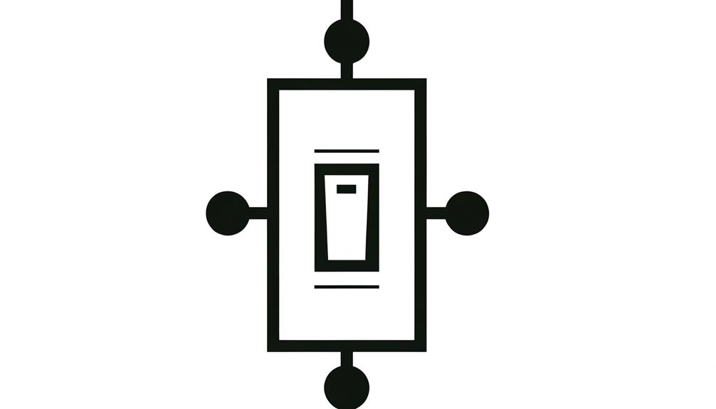
Single-pole switches function as binary devices that control a circuit by either completing or interrupting the electrical flow to a load. These switches are characterized by having a single input and a single output terminal, which makes their operation straightforward.
When the switch is in the 'on' position, it closes the circuit, allowing current to flow uninterrupted. Conversely, when in the 'off' position, the switch opens the circuit, thereby halting the current. This basic functionality is critical in residential and commercial electrical systems where simple on/off control is required.
The symbol for a single-pole switch typically consists of a line intersecting a break, representing the switch's ability to open or close the circuit.
Common Wiring Configurations
Understanding the basic functionality of single-pole switches sets the stage for exploring the common wiring configurations used in residential and commercial applications. Single-pole switches are essential for controlling a single circuit and typically feature two terminals: one for the incoming hot wire and another for the outgoing hot wire to the load. This configuration ensures a direct connection that interrupts the electrical flow when toggled.
| Configuration | Description | Typical Use Case |
|---|---|---|
| Single-Pole | One switch controls one load | Standard lighting circuits |
| Three-Way | Two switches control one load | Staircases, large rooms |
| Four-Way | Three or more switches control one load | Hallways, complex layouts |
| Double-Pole | Controls two circuits simultaneously | High-power devices, HVAC |
| Dimmer | Adjusts light intensity | Variable lighting environments |
This table elucidates various switch configurations, emphasizing single-pole simplicity.
Practical Applications Overview
In residential electrical systems, the single-pole switch's simplicity and reliability make it indispensable for controlling individual lighting circuits and small appliances. Typically denoted by a single line and a break or gap in schematic diagrams, this switch operates by opening or closing a single electrical pathway.
Its straightforward mechanism involves two terminals: one for the incoming hot wire and one for the outgoing load wire. When the switch is toggled, it either completes or interrupts the circuit, thereby controlling the flow of current to the connected device.
This fundamental operation underscores its widespread use in household applications, where it serves as a primary interface for user-initiated control over electrical loads, ensuring both functionality and safety in everyday environments.
Double-Pole Switch
A double-pole switch, also known as a DPST (Double Pole Single Throw) switch, is a critical component in electrical engineering that simultaneously controls two separate circuits.
This type of switch is characterized by its ability to open or close two independent circuits through a single actuator. The DPST switch is often employed in applications requiring the isolation of two distinct electrical paths, ensuring synchronized operation.
Electrical diagrams represent the DPST switch with two interconnected sets of contacts, each denoted by its own pole. This configuration is advantageous in scenarios demanding reliable disconnection or connection of dual-voltage systems, such as in household appliances or industrial machinery, where safety and efficiency are paramount.
Accurate utilization of a DPST switch enhances system reliability and operational integrity.
Momentary Switch Symbols
Momentary switch symbols are pivotal in accurately representing transient contact states in circuit diagrams, important for types such as normally open (NO) and normally closed (NC) configurations.
These symbols facilitate precise schematic interpretations, significant for applications in control panels, push-button operations, and automated systems.
Understanding the nuances of these symbols enables engineers to design circuits with reliable and predictable momentary interactions.
Types of Momentary Switches
Understanding the different types of momentary switches is essential for designing and interpreting electrical schematics accurately. Momentary switches, characterized by their temporary contact state, serve various functional purposes in circuits. Below is a detailed table outlining common types and their operational mechanics:
| Switch Type | Description |
|---|---|
| SPST (Single Pole Single Throw) | Simplest form, makes or breaks single connection. |
| SPDT (Single Pole Double Throw) | Connects a common terminal to one of two other terminals. |
| DPST (Double Pole Single Throw) | Controls two circuits simultaneously with a single action. |
| DPDT (Double Pole Double Throw) | Switches two circuits between two states. |
| Push-to-Make (Normally Open) | Completes circuit when pressed, returns open when released. |
Each type serves unique applications, necessitating precise symbol representation for accurate schematic interpretation.
Circuit Diagram Representation
In circuit diagrams, momentary switch symbols are vital for conveying the specific type of switch and its operational characteristics. These symbols often depict a combination of lines, dots, and arrows to denote the switch's momentary nature—indicating that it returns to its default state post-actuation.
Typically, a normally open (NO) momentary switch is represented by a line intersecting another line at an angle, often accompanied by an arrow pointing away from the switch. Conversely, the normally closed (NC) variant is illustrated with a similar configuration but includes a small break in the line to denote its default closed state.
Understanding these symbols is crucial for accurately interpreting and designing electrical circuits, ensuring proper functionality and safety.
Common Applications Explained
Momentary switch symbols play an essential role in various applications, including industrial control systems, consumer electronics, and automotive systems, where precise, on-demand actions are required. These switches are designed to remain in their default state until actuated, reverting immediately after release. Understanding these symbols is vital for designing and troubleshooting circuits with high precision and reliability.
| Application | Example Devices | Symbol Representation |
|---|---|---|
| Industrial Control | Emergency Stop, Start Buttons |  |
| Consumer Electronics | Keyboards, Power Buttons |  |
| Automotive Systems | Horns, Ignition Start Switches |  |
In industrial contexts, momentary switches ensure safety and operational efficiency. In consumer electronics, they offer user-friendly interfaces, while in automotive systems, they provide essential control functions. Understanding these applications enhances the ability to design and deploy effective electrical systems.
Switch Symbols in Schematics
Electrical schematics utilize a variety of symbols to represent different types of switches, each conveying specific operational characteristics and functionalities. These symbols are fundamental for engineers and technicians to accurately interpret and construct electrical circuits.
Key symbols include:
- Single-Pole Single-Throw (SPST) Switch: Represented by a simple break in a line, denoting an on-off function.
- Single-Pole Double-Throw (SPDT) Switch: Illustrated by a break with a connection to two alternate paths, indicating changeover functionality.
- Double-Pole Double-Throw (DPDT) Switch: Shown as two SPDT switches operated by a single mechanism, facilitating complex switching tasks.
Each symbol's precise representation guarantees standardized communication in schematic diagrams, allowing for efficient troubleshooting, design, and implementation in various electrical systems.
Practical Applications
Engineers and technicians leverage these switch symbols across various industries to design and implement reliable control systems in applications ranging from consumer electronics to industrial automation.
In consumer electronics, switches control power distribution within devices, ensuring efficient operation. Industrial automation utilizes switch symbols in Programmable Logic Controllers (PLCs) and Human-Machine Interfaces (HMIs) to manage complex machinery operations.
Switch symbols are integral to circuit diagrams, streamlining diagnostics and maintenance by providing clear, standardized representations. Additionally, automotive engineering employs switch symbols to design and troubleshoot electrical systems within vehicles.
The versatility of switch symbols, from enabling simple light control to orchestrating sophisticated, multi-component systems, underscores their critical role in electrical schematics, driving innovation and efficiency across technological domains.
Conclusion
To sum up, understanding the electrical symbols for various types of switches is crucial in electrical schematics. Mastery of these symbols, from single-pole to momentary switches, is vital for accurate circuit design and troubleshooting.
The complexity and variety of switch symbols can appear dauntingly detailed, yet they are the cornerstone of effective electrical engineering. Proficiency in interpreting these symbols guarantees clarity and functionality in practical applications, ultimately leading to the peak of electrical system efficiency.