How to Identify the Electrical Symbol for a Solenoid in Circuit Diagrams
The electrical symbol for a solenoid is crucial for accurately representing this electromechanical device in circuit diagrams. Usually, it comprises a rectangle with a diagonal line or an 'S' shape inside, indicating a magnetic coil.
The symbol highlights the solenoid's function in converting electrical energy into linear motion. Proper depiction helps prevent misinterpretation, improving system integrity and functionality.
Different versions exist based on particular applications and industry norms. Accurate use of standard symbols guarantees the clarity and precision of circuit designs.
Refer to detailed diagrams and a more in-depth exploration of optimal techniques and typical challenges.
Key Takeaways
- The electrical symbol for a solenoid typically consists of a coil symbol with a straight line representing the plunger.
- It may be depicted as a series of loops (coil) with a line or arrow indicating motion.
- Accurate symbols are crucial to ensure proper identification and understanding in circuit diagrams.
- Misinterpretation of symbols can lead to errors in designing and troubleshooting electrical systems.
- Adhering to standard symbol conventions is essential for clarity and consistency in technical documentation.
What Is a Solenoid?
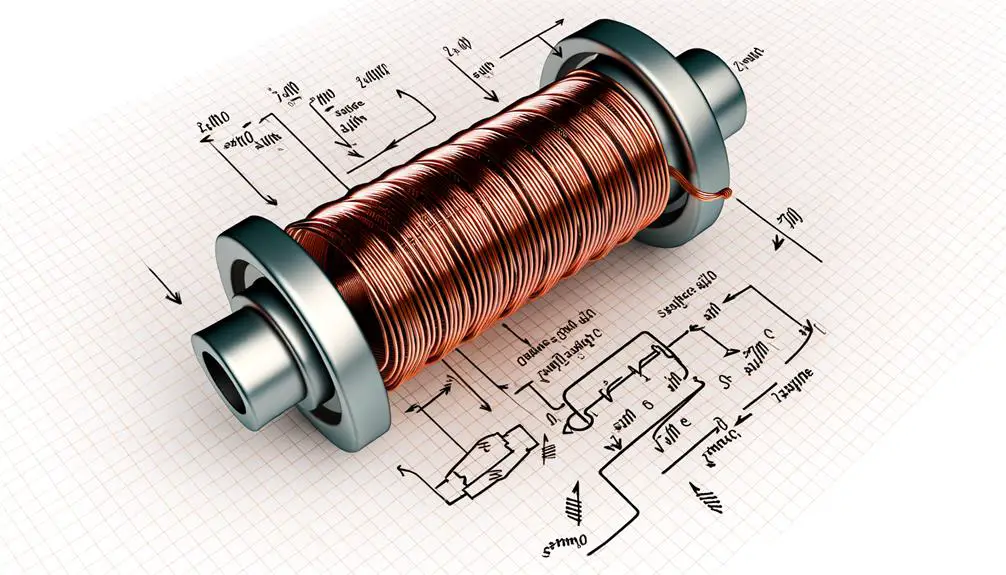
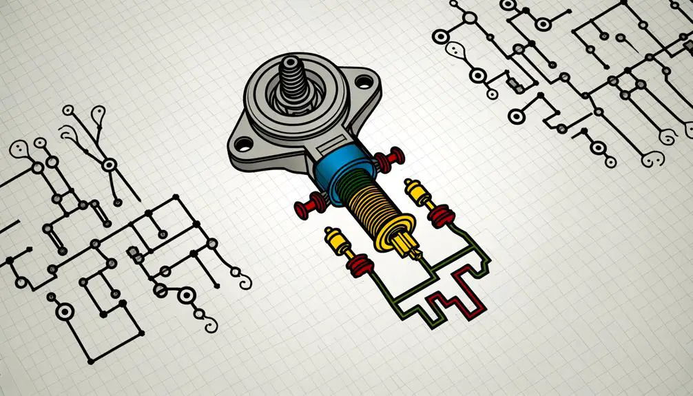
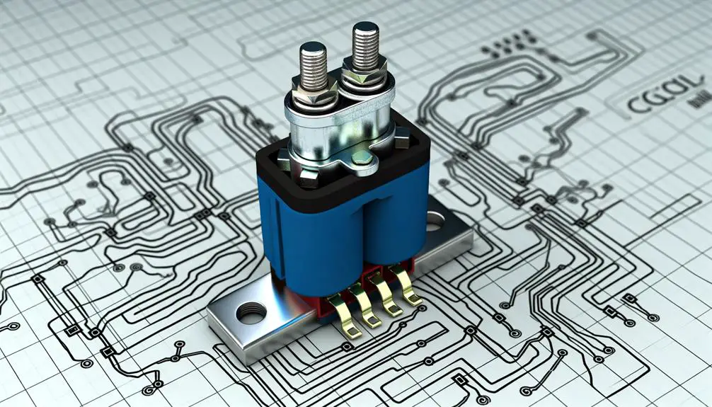
A solenoid is an electromechanical device that converts electrical energy into linear motion, typically consisting of a coil of wire wound around a movable iron core. This configuration creates a magnetic field when an electric current passes through the coil, causing the iron core to move.
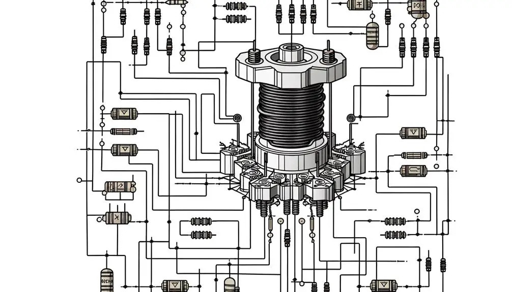
The solenoid's structure usually includes a cylindrical housing, an armature, and return springs, which guarantee precise control of the core's movement. Detailed diagrams often depict the electrical connections, magnetic field lines, and mechanical components, aiding in understanding the device's operation.
Solenoids are used in various applications, such as actuators in automotive systems, industrial machinery, and electronic locks, due to their reliability, efficiency, and rapid response to electrical signals.
Solenoid Functionality
Understanding solenoid functionality requires an examination of electromagnetic coil basics. Electric current passing through a wire coil generates a magnetic field. This magnetic field is essential for the solenoid's operation, enabling it to convert electrical energy into mechanical motion.
Detailed diagrams will illustrate its diverse applications in devices such as valves, actuators, and relays.
Electromagnetic Coil Basics
Solenoids, as a specific application of electromagnetic coils, convert electrical energy into linear mechanical motion through the creation of a magnetic field when electrical current passes through the winding. This magnetic field exerts a force on a movable ferromagnetic core, resulting in precise mechanical displacement.
Essential components include:
- Winding (coil): A wire, typically copper, wound into a helical shape to generate a magnetic field.
- Ferromagnetic core (plunger): A movable metal piece that responds to the magnetic field.
- Housing: Encases the coil and core, providing structural support and protection.
Understanding these basics allows for accurate analysis of solenoid operation, aiding in troubleshooting and design. Detailed diagrams often illustrate these components, enhancing comprehension for those seeking in-depth knowledge.
Magnetic Field Generation
When electrical current flows through the winding of a solenoid, it generates a magnetic field that is concentrated along the axis of the coil. The magnetic field strength (B) within the solenoid is directly proportional to the current (I) and the number of turns per unit length (n) of the coil. This relationship can be described by the formula \( B = \mu_0 n I \), where \( \mu_0 \) is the permeability of free space. The table below highlights key parameters influencing the magnetic field generation in a solenoid:
| Parameter | Symbol | Unit |
|---|---|---|
| Current | I | Amperes (A) |
| Number of Turns | n | turns/meter |
| Magnetic Field | B | Tesla (T) |
| Permeability | \( \mu_0 \) | Henry/meter (H/m) |
| Length of Coil | L | meters (m) |
Understanding these parameters is essential for optimizing solenoid design and functionality.
Applications in Devices
The magnetic field generated by a solenoid is harnessed in various devices to achieve functionalities such as actuation, electromagnetic locking, and precise control of fluid flow. This versatile component is essential in numerous applications due to its ability to generate a controlled magnetic field.
- Actuation: Solenoids are used in linear actuators for precise mechanical movements, vital in automation systems.
- Electromagnetic Locking: Employed in security systems, solenoids provide reliable locking mechanisms that can be remotely controlled.
- Fluid Control: Solenoid valves regulate the flow of liquids and gases in industrial processes, offering high precision and responsiveness.
These applications underscore the solenoid's importance in modern technology, demanding a thorough understanding of its electrical and magnetic properties.
Importance in Circuits
A solenoid's electrical symbol plays an important role in circuit diagrams, providing a clear and standardized representation essential for accurate communication among engineers and technicians. This symbol guarantees that the solenoid's function within the circuit is immediately recognizable, aiding in efficient troubleshooting and system analysis.
Precise terminology and detailed diagrams are indispensable, as they prevent misinterpretations that could lead to circuit failures or malfunctions. The symbol typically consists of a coil, indicating the solenoid's electromagnetic nature, and often includes annotations specifying voltage and current ratings.
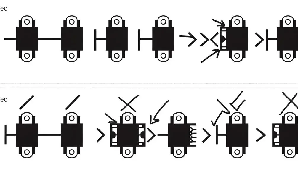
Basic Symbol Description
How is the solenoid symbolically represented in electrical schematics to ensure clear communication and accurate functionality?
The solenoid is depicted by a coil of wire, often shown as a series of loops or a rectangle with a line through it, indicating the electromagnetic nature of the device. This symbol guarantees engineers can easily identify and implement solenoids within circuits.
Key characteristics of the solenoid symbol include:
- Coil Representation: Depicted as a series of loops or a rectangle, symbolizing the coil of wire.
- Magnetic Field Indicator: A line through the coil signifies the magnetic field generated when current flows.
- Terminals: Clearly marked connection points to indicate where the solenoid connects within the circuit.
This precise representation is essential for accurate circuit design and interpretation.
Variations of the Symbol
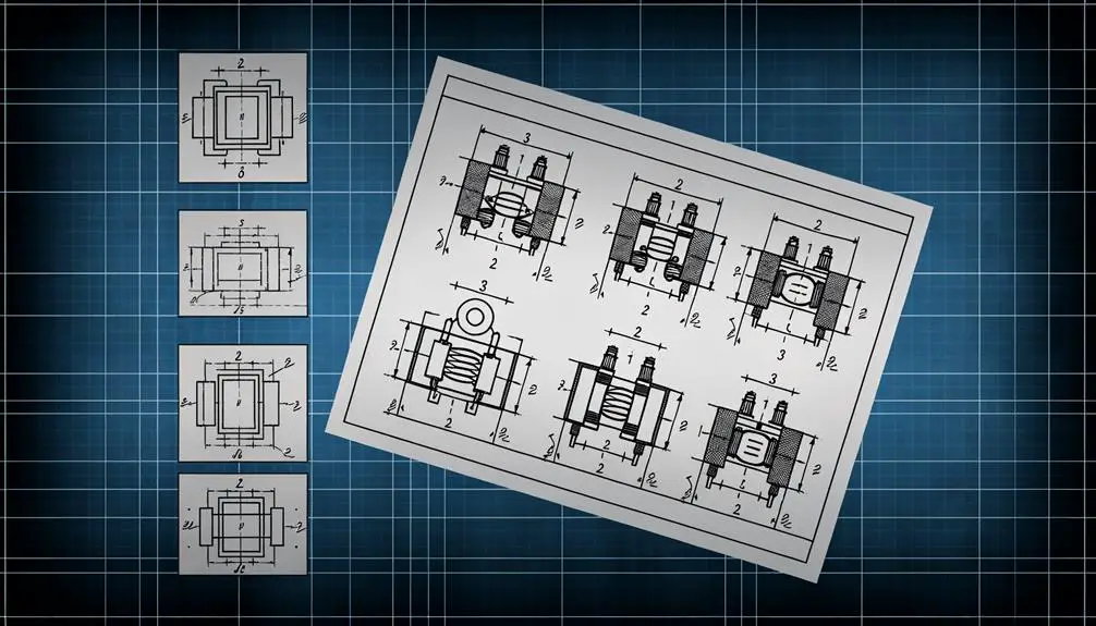
Beyond the basic depiction, variations of the solenoid symbol exist to represent specific types and configurations, such as solenoids with integrated diodes or different core materials. These variations provide clarity in circuit diagrams, ensuring precise understanding of each solenoid's functionality. For instance, a solenoid with an integrated diode may include a small triangle and line symbol, indicating the diode's presence. Distinct symbols also exist for solenoids with different core materials, such as iron or air. The following table summarizes these variations:
| Symbol Type | Description | Example Usage |
|---|---|---|
| Basic Solenoid | Standard solenoid | General electrical circuits |
| Solenoid with Diode | Solenoid with integrated diode | Overvoltage protection |
| Solenoid with Iron Core | Solenoid with iron core | Electromagnetic applications |
These variations enhance diagrammatic precision and practical application.
Reading Circuit Diagrams
Understanding circuit diagrams requires familiarity with electrical symbols and the ability to interpret the relationships between different components accurately. This skill is essential for diagnosing and troubleshooting electrical circuits.
For effective reading, one must:
- Identify Symbols: Recognize and understand the various symbols, such as resistors, capacitors, and solenoids, used in the diagram.
- Follow Connections: Trace the paths of electrical connections between components to comprehend how current flows through the circuit.
- Analyze Function: Determine the purpose of each component within the circuit's context, aiding in understanding the overall system operation.
Technical accuracy and precise terminology are paramount. Detailed diagrams enhance comprehension, providing visual confirmation of textual descriptions.
Mastery of these principles empowers individuals to navigate complex electrical schematics proficiently.
Practical Applications
The application of solenoids spans various sectors, including industrial automation, automotive system integration, and robotics.
In industrial automation, solenoids are essential for controlling valves and actuating mechanical processes.
Automotive systems leverage solenoids for functions like fuel injection and automatic transmission.
In robotics, solenoids serve as precise actuators for movement and control.
Industrial Automation Uses
In industrial automation, solenoids are essential components used for actuating valves, controlling fluid flow, and performing precise mechanical movements. These electromechanical devices convert electrical energy into linear motion, enabling a wide array of operational functionalities.
Their applications include:
- Valve Actuation: Solenoids control the opening and closing of valves in fluid systems, ensuring precise flow regulation.
- Locking Mechanisms: They secure machinery components, providing safety and operational stability.
- Pneumatic and Hydraulic Systems: Solenoids manage air or fluid pressure, crucial for the functioning of automated systems.
The detailed diagrams of solenoid configurations in these systems highlight their versatility and crucial role in enhancing automation efficiency. Understanding these uses is essential for designing and optimizing industrial automation solutions.
Automotive System Integration
Integration of solenoids in automotive systems exemplifies advanced engineering, facilitating functions such as fuel injection, transmission control, and anti-lock braking. These electromechanical devices convert electrical energy into mechanical motion, enabling precise control over various automotive components.
In fuel injection systems, solenoids actuate injectors, ensuring prime fuel delivery and combustion efficiency. Transmission systems utilize solenoid valves to manage hydraulic circuits, achieving smooth gear shifts. Anti-lock braking systems (ABS) employ solenoids to modulate brake pressure, preventing wheel lockup and enhancing vehicle safety.
Detailed diagrams of these integrations reveal the solenoid's role in automotive circuitry, highlighting their importance in maintaining performance and reliability. Understanding these applications underscores the critical nature of solenoids in modern vehicular technology.
Robotics and Actuators
Solenoids serve as critical actuators in robotics, enabling precise and reliable control over mechanical movements through electromagnetic force. Their practical applications in robotics are numerous, including:
- Linear Actuation: Solenoids provide linear motion essential for tasks such as gripping, lifting, and pushing.
- Valve Control: They regulate fluid flow in hydraulic and pneumatic systems, integral to robotic arms and automated systems.
- Locking Mechanisms: Solenoids act as secure locking devices in robotic assemblies, ensuring components remain in place during operation.
Industry Examples
Various industries utilize solenoids in applications ranging from automated manufacturing systems to medical devices, demonstrating the versatility and importance of these electromagnetic components.
In automotive engineering, solenoids are integral to fuel injection systems, providing precise control over fuel delivery.
In industrial automation, solenoids actuate valves in fluid control systems, ensuring efficient operation.
Medical devices, such as MRI machines, rely on solenoids for precise magnetic field control.
Additionally, in telecommunications, solenoids are used in relay systems to route signals accurately.
Each application demands specific solenoid characteristics, such as voltage ratings and response times, tailored to meet the rigorous standards of the respective industry.
Detailed diagrams of these applications often illustrate the solenoid's role within complex systems.
Common Mistakes
Inaccurate depiction of the solenoid symbol is a frequent error, often leading to confusion and malfunction in electrical systems.
Additionally, misinterpreting circuit diagrams can result in incorrect connections, compromising the integrity and functionality of the entire system.
Detailed diagrams and precise terminology are crucial to avoid these common pitfalls and guarantee proper implementation.
Incorrect Symbol Usage
One prevalent error in electrical schematics is the misuse of symbols that closely resemble the correct solenoid representation, leading to potential misinterpretations in circuit design. Accurate symbol usage is vital for ensuring that the intended function of the solenoid is understood.
Common mistakes include:
- Confusing with Inductors: Inductors and solenoids share similar visual symbols but serve different purposes.
- Mislabeling with Valves: Solenoids in hydraulic or pneumatic systems can be confused with valve symbols, affecting system interpretation.
- Overlooking Polarity Indicators: Omitting or incorrectly placing polarity indicators can lead to improper solenoid operation.
Adherence to standard symbol conventions and careful attention to detail are essential to avoid these pitfalls, ensuring clarity and precision in schematic diagrams.
Misinterpreting Circuit Diagrams
Misinterpreting circuit diagrams often stems from a lack of familiarity with standardized symbols and conventions, leading to errors that can compromise the functionality and safety of electrical systems. Common mistakes include misidentifying components like solenoids, resistors, or capacitors due to incorrectly drawn or outdated symbols.
Additionally, failing to observe the correct orientation or connection points in the diagrams can result in short circuits or unintended operational behaviors. Properly interpreting a solenoid's symbol, which typically includes a coil with an iron core, is essential for ensuring its correct integration into the circuit.
To avoid these pitfalls, it is vital to reference up-to-date standards, such as IEEE or IEC guidelines, and to cross-verify with detailed, accurate schematics.
Troubleshooting Tips
When troubleshooting a solenoid circuit, start by verifying the integrity of the electrical connections and confirming that the voltage supply meets the specified requirements. Accurate assessment involves the following steps:
- Inspect Wiring: Check for loose, frayed, or corroded wires. Confirm all connections comply with the circuit diagram.
- Measure Voltage: Use a multimeter to confirm that the voltage at the solenoid terminals matches the design specifications. Inconsistent voltage can indicate power supply issues.
- Check Resistance: Measure the coil resistance with an ohmmeter. Compare readings to the manufacturer's specifications to detect potential coil damage or shorts.
Advanced Uses
Advanced applications of solenoids encompass their integration into automated systems, precise actuation mechanisms, and complex electromagnetic devices.
In automated systems, solenoids provide rapid and reliable switching for valves and relays, enhancing efficiency and control.
Precise actuation mechanisms benefit from solenoids' ability to deliver controlled linear motion, essential in robotics and precision machinery.
Complex electromagnetic devices, such as MRI machines, exploit solenoids to generate uniform magnetic fields for imaging.
Detailed diagrams often illustrate solenoid configurations, highlighting coil windings, magnetic cores, and electrical connections.
Understanding these advanced uses requires familiarity with electromagnetic principles, circuit design, and system integration.
This knowledge enables engineers to leverage solenoids' capabilities in developing sophisticated, high-performance applications.
Conclusion
To conclude, understanding the electrical symbol for a solenoid is crucial for designing effective circuits, ensuring proper functionality, and avoiding common errors.
Recognizing variations of the symbol can facilitate accurate interpretation in diverse industry applications. By adhering to standard representations, circuit designers can enhance reliability, improve troubleshooting efficiency, and leverage advanced uses of solenoids for innovative solutions.
Mastery of these symbols is essential for achieving technical precision and optimizing circuit performance.