Electrical Symbol for a Relay in Schematics?
The electrical symbol for a relay provides essential insights into its electromagnetic switching capabilities and contact arrangements. Typically, it comprises a rectangle representing the coil and lines illustrating the contacts, which may be usually open (NO) or usually closed (NC).
Different configurations such as SPST, SPDT, DPST, and DPDT are represented to denote specific operational behaviors. Accurate interpretation of these symbols guarantees proper relay operation and system reliability.
Understanding these symbols is fundamental for effective circuit design, efficient troubleshooting, and maintaining system integrity. By exploring further, one can master the complexities and applications of various relay systems in electrical engineering.
Key Takeaways
- The relay symbol includes a rectangle representing the coil and lines depicting the contacts.
- Contact symbols show configurations like normally open (NO) and normally closed (NC).
- Common contact configurations include SPST, SPDT, DPST, and DPDT.
- Ensure coil voltage ratings match the control circuit for proper relay operation.
- Standardized relay symbols aid in clear circuit diagram communication and troubleshooting.
Relay Symbol Basics
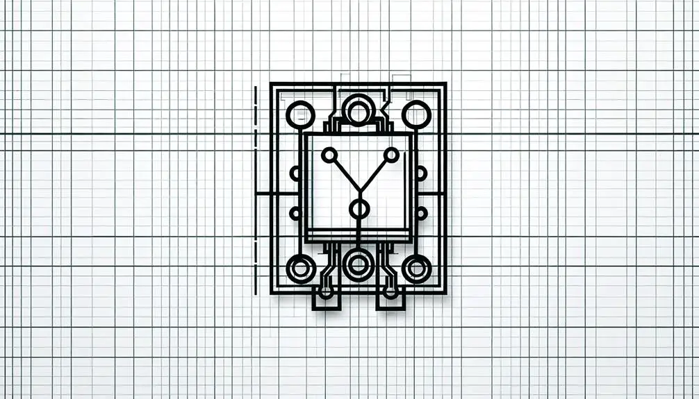
A relay symbol in electrical schematics is a graphical representation that denotes the function and configuration of a relay within a circuit. It provides vital visual information about the relay's electromagnetic switching capabilities, necessary contact arrangements, and coil connections.
Typically, the symbol consists of a rectangle indicating the relay coil, accompanied by lines representing the movable and fixed contacts. These lines may be depicted as normally open (NO), normally closed (NC), or changeover (CO) states, reflecting the relay's default position without electrical activation.
The schematic symbol serves as a universal language for engineers and technicians, ensuring precise communication of the relay's role and integration within complex electrical systems. Accurate interpretation of these symbols is essential for effective circuit design and troubleshooting.
Types of Relay Symbols
The types of relay symbols encompass various configurations, including coil and contact symbols, which are fundamental to understanding relay functionality in circuit diagrams.
Single pole relays are represented with a single contact mechanism, while double pole relays feature two separate contact mechanisms within the same relay.
Each symbol type provides critical information regarding the relay's switching capabilities and operational characteristics.
Coil and Contact Symbols
Understanding the coil and contact symbols used in relay schematics is essential for accurately interpreting and designing electrical circuits. The coil symbol, typically represented by a rectangle or an oval, denotes the electromagnetic coil that actuates the relay.
Contacts, on the other hand, are depicted by lines that indicate their operational state—normally open (NO) or normally closed (NC). A NO contact remains open until the relay coil is energized, while an NC contact remains closed until the coil is energized.
Detailed representations often include the contact type (SPDT, DPDT) and the switching mechanism. Mastery of these symbols allows engineers to efficiently troubleshoot, design, and communicate circuit functionalities, ensuring precise and reliable relay operations.
Single Pole Relay
Single pole relays, commonly referred to as SP relays, are fundamental components in electrical systems, characterized by their ability to control a single circuit with a single switch. These relays function by energizing a coil that actuates a single set of contacts, either opening or closing the circuit.
In schematic diagrams, SP relays are typically represented by a rectangular symbol for the coil and a single line or set of lines for the contacts. The contacts may be shown in their default state, normally open (NO) or normally closed (NC), indicating how the relay operates when de-energized.
This straightforward design makes SP relays ideal for applications requiring simple on/off control, enhancing reliability and ease of understanding in circuit designs.
Double Pole Relay
Double pole relays, often abbreviated as DP relays, are integral components in electrical systems, capable of simultaneously controlling two separate circuits with a single coil actuation.
These relays feature two sets of contacts, which can be either normally open (NO) or normally closed (NC). When the coil is energized, both sets of contacts change state concurrently, enabling the relay to manage independent electrical pathways.
The electrical symbol for a DP relay typically includes two sets of switch contacts, each represented by a pair of lines, alongside the coil symbol. This configuration allows for clear identification in circuit diagrams, ensuring precise implementation.
DP relays are essential for applications requiring coordinated control of multiple circuits, enhancing functionality and reliability.
Interpreting Relay Symbols
Interpreting relay symbols is crucial for understanding their contact configuration types. These include:
- Single Pole Single Throw (SPST)
- Single Pole Double Throw (SPDT)
- Double Pole Single Throw (DPST)
- Double Pole Double Throw (DPDT).
Additionally, coil voltage ratings must be accurately identified to guarantee compatibility with the intended electrical system.
Comprehending the functionality and applications of various relays enables the effective integration of these components in circuit designs.
Contact Configuration Types
Understanding the contact configuration types is essential for accurately interpreting relay symbols, as these configurations determine the relay's operational behavior and connectivity within an electrical circuit. Contacts are categorized based on their default state and number of circuits they control. The most common types are Single Pole Single Throw (SPST), Single Pole Double Throw (SPDT), Double Pole Single Throw (DPST), and Double Pole Double Throw (DPDT).
| Configuration | Description |
|---|---|
| SPST | Single circuit, on/off switching |
| SPDT | Single circuit, switch between two paths |
| DPST | Two circuits, on/off switching |
| DPDT | Two circuits, switch between two paths |
Each configuration offers distinct advantages, influencing the design and functionality of electrical systems.
Coil Voltage Ratings
An essential aspect of interpreting relay symbols involves understanding the coil voltage ratings, which specify the voltage required to energize the relay coil and enable the switching mechanism. Coil voltage ratings are crucial for ensuring compatibility with the control circuit.
Typical ratings can range from as low as 5V DC to as high as 240V AC, depending on the relay's design and application. Misinterpretation of these ratings can lead to insufficient energization, causing the relay to malfunction or even fail.
Engineers must carefully select relays with appropriate coil voltage ratings to match the intended control voltage, ensuring reliable operation. Accurate interpretation of these ratings is important for the correct implementation and optimum performance of relay-based circuits.
Functionality and Applications
Relays play a vital role in various applications by enabling the control of high-power circuits through low-power signals, and their symbols offer crucial insights into their functionality and integration within electrical systems.
The relay symbol typically shows a coil that, when energized, triggers one or more switch contacts. These contacts can be either normally open (NO) or normally closed (NC), indicating their state when the coil is not energized.
The symbol's annotation often includes the coil voltage rating and contact arrangement, essential for grasping the relay's operational parameters. Interpreting these symbols accurately guarantees proper relay selection and integration, aiding in reliable circuit control in automation, telecommunications, and industrial systems.
This comprehension is essential for designing efficient and sturdy electrical solutions.
Common Relay Configurations
A variety of relay configurations, including single-pole single-throw (SPST), single-pole double-throw (SPDT), double-pole single-throw (DPST), and double-pole double-throw (DPDT), are commonly employed in electrical circuits to control multiple outputs and ensure operational flexibility. These configurations enable precise control of electrical loads, ensuring that circuits can be designed for specific operational requirements. Below is a table that delineates the key characteristics of these relay configurations:
| Configuration | Number of Poles | Number of Throws |
|---|---|---|
| SPST | 1 | 1 |
| SPDT | 1 | 2 |
| DPST | 2 | 1 |
| DPDT | 2 | 2 |
Understanding these configurations is essential for selecting the appropriate relay type to meet specific circuit demands.
Importance in Circuit Design
In circuit design, the strategic implementation of relays is important for achieving reliable and efficient control of electrical loads and signal routing.
Relays allow circuits to switch between different states, enabling the control of high-power loads with low-power signals. This is critical in applications requiring isolation between control and load circuits, preventing direct electrical connections that could lead to faults or interference.
Relays also facilitate the automation of complex systems, making sure that multiple circuit paths can be managed effectively.
The accurate representation of relays in schematics ensures a clear understanding of the circuit's operational dynamics, which is essential for troubleshooting, maintenance, and optimization. Therefore, relays are indispensable components in modern circuit design.
Tips for Accurate Schematics
Ensuring the accuracy of schematics involves adhering to standardized symbols and conventions, which play a pivotal role in accurately conveying circuit functionality and facilitating effective communication among engineers.
To achieve this, it is necessary to utilize universally recognized symbols, such as those defined by ANSI or IEC standards. Clear labeling of components, including relays, resistors, and capacitors, is essential for avoiding ambiguity.
Consistent use of line styles to denote different types of connections (e.g., power, signal) aids in readability. Moreover, maintaining a logical flow by organizing components systematically, often from left to right or top to bottom, enhances comprehension.
Regularly updating and cross-referencing the schematic against the physical circuit guarantees accuracy and reliability in design documentation.
Conclusion
The understanding and accurate interpretation of relay symbols are crucial for precise circuit design and effective communication within the field of electrical engineering.
Despite the expected objection regarding the lack of visual aids, the detailed textual explanation provided herein guarantees a thorough understanding of relay symbols and their configurations.
Mastery of these symbols facilitates the creation of precise schematics, thereby improving the reliability and efficiency of electronic circuits.