Identifying and Drawing the Electrical Symbol for a Fuse
The electrical symbol for a fuse is depicted as a straight line intersected by a small rectangle, emphasizing its role in overcurrent protection. This symbol varies based on fuse types and international standards such as IEC and ANSI.
Fuses play a pivotal role in shielding circuits from excessive current, thereby preventing potential fire hazards and enhancing system reliability. Common fuse types include fast-acting, time-delay, and resettable fuses.
Understanding these variations and adherence to standards like IEEE 315 and IEC 60617 is vital for accurate circuit design and maintenance. Further exploration will reveal detailed specifics and practical applications.
Key Takeaways
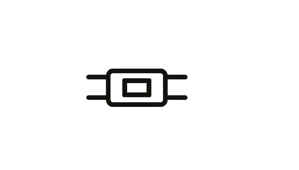
- The basic fuse symbol is a straight line intersected by a small rectangle.
- Fuse symbols vary by type, such as fast-acting or time-delay, and by standards like IEC and ANSI.
- North American fuse symbols often use a simple rectangle with a line.
- European IEC standards employ more complex symbols for different fuse types.
- Accurate fuse symbols in schematics prevent misidentification and facilitate troubleshooting.
Definition of a Fuse
A fuse is an electrical safety device designed to protect circuits from excessive current by melting and breaking the circuit when the current exceeds a predefined threshold. This operational principle is based on the thermal properties of specific materials, which are chosen to guarantee precise melting points.
Fuses are integral in preventing potential hazards such as electrical fires and component damage. They are composed of a conductive strip or wire housed in a non-combustible casing. When the current surpasses the safe limit, the heat generated causes the strip to melt, thereby interrupting the circuit.
Fuses are rated by their current-carrying capacity and voltage, ensuring compatibility with various electrical systems. They are critical in both residential and industrial applications for maintaining electrical safety.
Importance of Fuses
Fuses play a pivotal role in safeguarding electrical systems by preventing overcurrent conditions that could lead to significant hazards and equipment failure. Their primary function is to interrupt the flow of excessive current, thereby protecting circuits from potential damage and reducing the risk of fire. The importance of fuses can be analyzed through various dimensions:
| Aspect | Description |
|---|---|
| Protection | Shields circuits from overcurrent and short circuits. |
| Safety | Reduces the risk of fire and electrical accidents. |
| Reliability | Ensures consistent performance under fault conditions. |
| Cost-Effectiveness | Provides an affordable means of circuit protection. |
| Maintenance | Simplifies replacement and reduces downtime. |
Basic Fuse Symbol
The basic fuse symbol in electrical diagrams is typically represented by a simple line with an interrupting element, indicating its protective role in the circuit.
Standard symbol variations can occur depending on the specific type of fuse and the regional or industry-specific standards.
In circuit diagrams, this symbol is strategically placed to illustrate where overcurrent protection is implemented, ensuring safe and efficient circuit operation.
Simple Line Representation
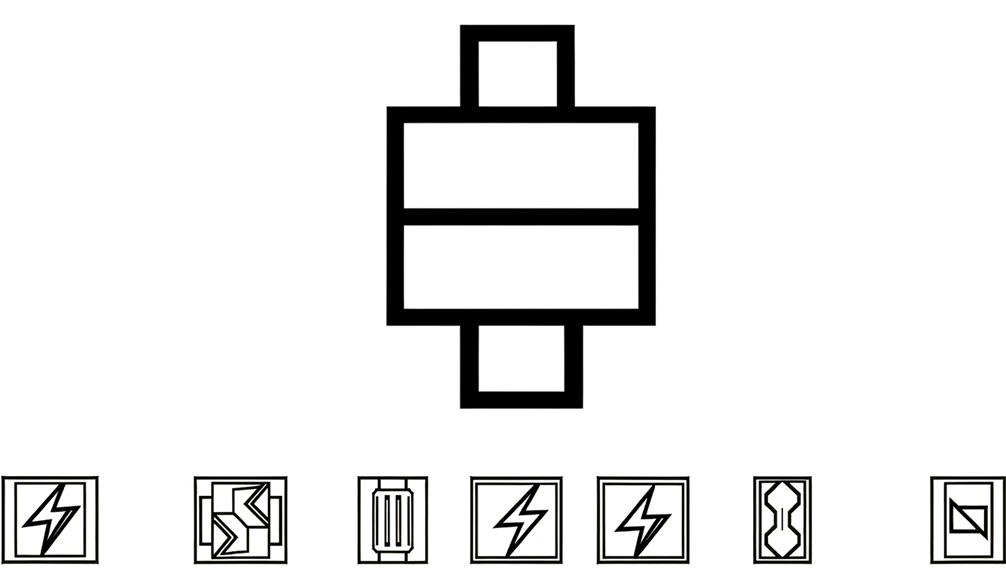
In electrical diagrams, the basic fuse symbol is often depicted as a simple straight line intersected by a small rectangle. This straightforward representation serves to indicate the presence of a fuse, an essential component for circuit protection.
The intersecting rectangle symbolizes the fusible link within the fuse, which melts when excessive current flows, thereby interrupting the circuit. The simplicity of this symbol facilitates quick recognition and understanding, vital for efficient circuit design and troubleshooting.
It is crucial that this symbol is accurately interpreted to guarantee the correct implementation of protective measures. The basic fuse symbol's minimalistic design underscores its fundamental role in maintaining electrical safety and operational integrity within various electrical systems.
Standard Symbol Variations
While the basic fuse symbol provides a foundation, various standard symbol variations exist to represent different types of fuses and their specific characteristics. These variations guarantee that the electrical schematics accurately convey essential information about the fuse type, rating, and application. For instance, symbols may differ for time-delay fuses, high-voltage fuses, and resettable fuses. These distinctions are essential for technicians and engineers who rely on precise diagrams to design and troubleshoot electrical systems.
| Fuse Type | Symbol Description |
|---|---|
| Time-Delay Fuse | A fuse symbol with a 'T' |
| High-Voltage Fuse | A fuse symbol with a 'H' |
| Resettable Fuse | A fuse symbol with a reset indicator |
Understanding these variations enhances the accuracy and safety of electrical system design and maintenance.
Circuit Diagram Usage
Basic fuse symbols are essential to circuit diagrams, providing clear indications of where protective elements are installed within electrical systems. These symbols, typically represented by a simple rectangle with a line through it, denote the presence of a fuse designed to protect electrical circuits from overcurrent conditions.
Accurate placement of fuse symbols on a diagram is pivotal for understanding the flow of electricity and identifying potential fault points. In more complex diagrams, variations of the basic symbol might be used to represent different fuse types, such as time-delay or high-rupture capacity fuses.
Clarity in these symbols aids engineers and technicians in diagnosing issues, ensuring safety, and maintaining system integrity. Understanding and using these symbols effectively is fundamental in electrical design and troubleshooting.
Variations of Fuse Symbols
Variations in fuse symbols arise from both standardization practices and regional differences. Standard fuse symbols are typically defined by international bodies like IEC and ANSI, but discrepancies can still occur across different geographical regions.
Understanding these variations is essential for accurately interpreting electrical schematics in a global context.
Standard Fuse Symbols
Standard fuse symbols encompass a range of variations designed to represent different types of fuses and their specific properties in electrical schematics. These symbols provide essential information for identifying fuse characteristics and guaranteeing proper circuit protection.
Common symbols include:
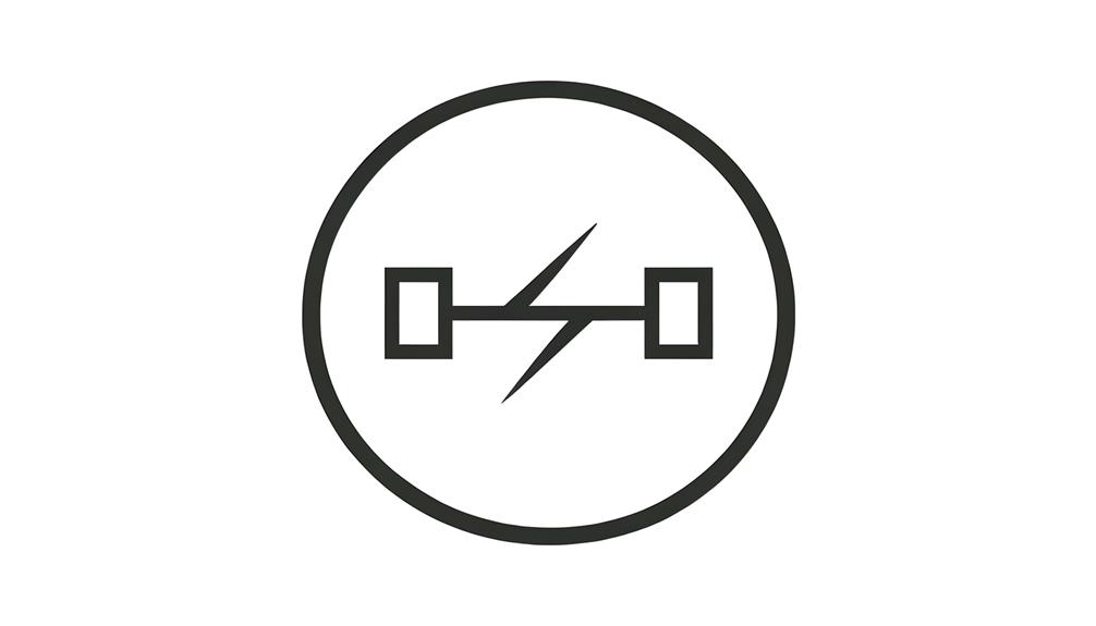
- Fast-acting fuse: A straight line intersected by a small rectangle, indicating rapid response to overcurrent.
- Slow-blow fuse: A similar straight line but with an additional curved line to denote delayed response.
- High-voltage fuse: A straight line with a small circle, representing fuses used in high-voltage applications.
- Resettable fuse: Depicted with a circular arrow, indicating the fuse can reset itself after tripping.
- Dual-element fuse: A combination of symbols showing both fast and slow characteristics for specific applications.
These variations secure precise communication of fuse types and their intended functions within electrical designs.
Regional Symbol Differences
Different regions may adopt distinct symbols for fuses in electrical diagrams, reflecting local standards and practices. In North America, the primary symbol for a fuse is a simple rectangle with a line through it.
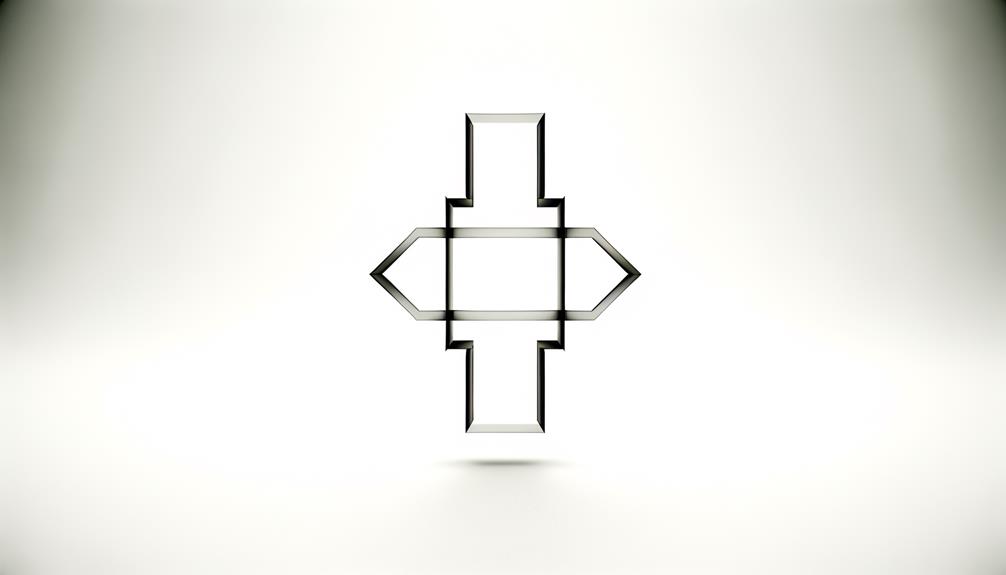
Conversely, European standards, such as those defined by IEC, use a more complex symbol resembling an hourglass or two opposing triangles. These variations are not merely aesthetic; they uphold compliance with regional regulatory frameworks and improve clarity for local engineers.
Understanding these differences is vital for professionals working in international contexts, as misinterpretation can lead to errors in design, safety issues, and non-compliance with regional codes. Engineers must be conversant with the specific symbols pertinent to the regions in which they operate.
Reading Fuse Symbols
Interpreting fuse symbols demands an understanding of the standardized graphic representations utilized in electrical diagrams. These symbols function as a universal language, offering crucial information at a glance. A typical fuse symbol is illustrated as a straight line with a horizontal line intersecting it, resembling an hourglass figure. The accuracy in interpreting these symbols is essential for precise circuit design and troubleshooting.
Key elements to recognize when interpreting fuse symbols include:
- Shape: Identifies the hourglass or rectangular shape.
- Labeling: Frequently contains letters/numbers indicating type and rating.
- Position: Indicates the fuse's location within the circuit.
- Size: Can signify the physical dimensions of the fuse.
- Configuration: Specifies whether the fuse is single or multiple elements.
Comprehending these elements guarantees reliable and safe electrical system operation.
Common Fuse Types
Fuses are available in a variety of types, each crafted to meet specific electrical protection needs and operational conditions.
These include fast-acting (or quick-blow) fuses, which respond rapidly to overcurrent conditions, providing immediate circuit protection.
Slow-blow (or time-delay) fuses, conversely, tolerate temporary surges, making them suitable for applications with inrush currents, such as motors.
Cartridge fuses, enclosed in a cylindrical body, are common in consumer electronics and automotive applications.
Blade fuses, recognized by their flat, pronged design, are prevalent in automotive systems.
Additionally, resettable fuses, or polymeric positive temperature coefficient (PPTC) devices, self-reset after an overload condition.
Each fuse type guarantees specific protection tailored to the unique demands of various electrical circuits and devices.
Fuse Symbol in Schematics
In electrical schematics, the fuse symbol is an important element that provides a visual representation of circuit protection components, guaranteeing engineers correctly interpret and implement safety measures. This symbol typically consists of a simplified depiction of the fuse's physical form, varying slightly across different schematic standards. Accurate representation is vital for the following reasons:
- Prevents component misidentification: Ensures that the fuse is not mistaken for other circuit elements.
- Facilitates troubleshooting: Aids in pinpointing where protection is provided within a circuit.
- Enhances safety: Clearly indicates protective devices that safeguard against overcurrent conditions.
- Supports standardization: Helps maintain consistency across different schematics and technical documents.
- Improves communication: Enables clear understanding among engineers, technicians, and stakeholders.
Standards for Fuse Symbols
Adhering to established standards for fuse symbols is essential for maintaining uniformity and accuracy in electrical schematics across various industries. Standards such as IEEE 315 and IEC 60617 specify graphical representations, guaranteeing that fuse symbols are universally recognized and correctly interpreted.
These standards detail aspects including shape, line thickness, and labeling conventions, thereby reducing the risk of misinterpretation. For instance, the IEEE 315 standard prescribes a simple rectangle with a diagonal line, while IEC 60617 employs a similar but subtly distinct symbol.
Compliance with these standards minimizes errors in design, manufacturing, and maintenance processes. By following these conventions, professionals maintain that electrical diagrams are both reliable and universally understandable, facilitating effective communication and operational efficiency.
Practical Examples
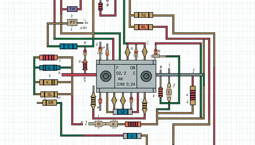
To illustrate the application of these standards, consider a practical example where IEEE 315 and IEC 60617 symbols are employed in a complex electrical schematic for an industrial control system. This system integrates multiple components for efficient operation.
The schematic includes:
- Power Distribution Panel: Utilizes IEEE 315 fuse symbols to indicate protective devices.
- Motor Control Center: Features IEC 60617 symbols for fuses safeguarding motor circuits.
- Programmable Logic Controller (PLC): Employs both standards for clarity in international projects.
- Safety Interlocks: Marked with fuse symbols to secure reliable fault protection.
- Instrumentation and Control Wiring: Uses standardized symbols to denote fuse protection in sensor circuits.
This example demonstrates how adhering to IEEE 315 and IEC 60617 standards guarantees clear, consistent, and internationally understood electrical diagrams.
Conclusion
Fuses serve as crucial safeguards in electrical circuits, protecting against overcurrents and potential hazards. The basic and variant symbols of fuses, while straightforward, are necessary for accurate schematic interpretations.
Understanding these symbols is essential for engineers and technicians alike, ensuring adherence to standardized norms and facilitating effective circuit design.
The juxtaposition of the fuse's simplicity with its crucial role in electrical safety underscores its fundamental importance in both theoretical and practical applications.