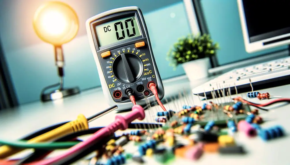
DC Voltage Symbol on a Multimeter: What Is It?
The DC voltage symbol on a multimeter is identified by a 'V' with a straight line above or beside it. This symbol is crucial for accurately measuring direct current (DC) voltage, which is pivotal for diagnosing and troubleshooting electronic components.
Correct usage involves selecting the appropriate voltage setting, ensuring proper probe placement, and interpreting the readings accurately. Mistakes such as improper probe connections or incorrect DC setting selections can lead to inaccurate measurements.
Regular maintenance like calibration and probe inspection is essential for reliable performance. Enhancing your multimeter skills can notably improve your diagnostic and troubleshooting efficacy.
Key Takeaways
- The DC voltage symbol on a multimeter is 'V' with a straight line above it.
- Ensure the multimeter is set to the DC voltage symbol before measuring DC circuits.
- The DC voltage symbol differentiates from the AC voltage symbol, which has a wavy line.
- Properly connecting probes is essential for accurate DC voltage measurements.
- Familiarity with the DC voltage symbol helps prevent incorrect measurements and potential damage.
Understanding Multimeter Basics
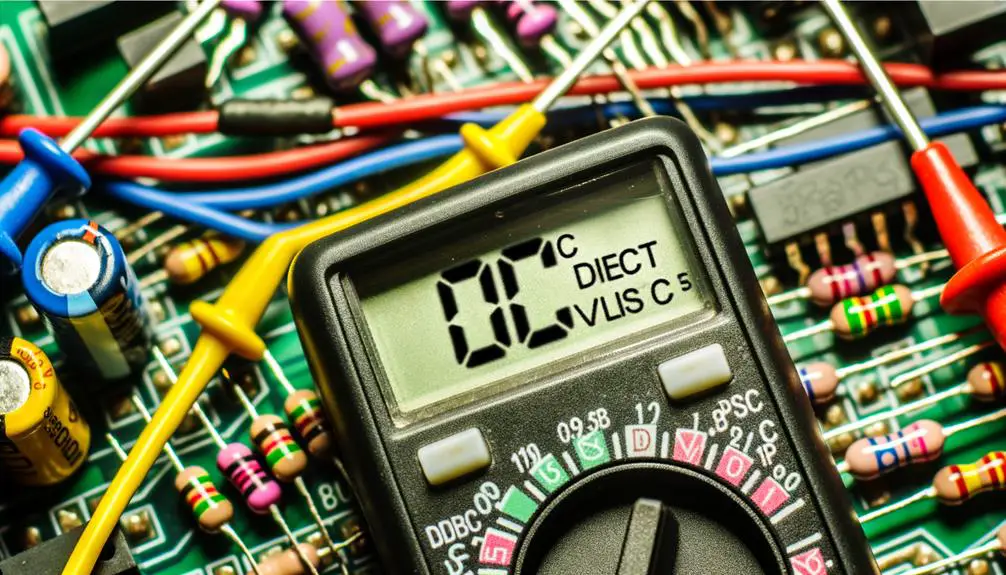
Understanding multimeter basics involves familiarizing oneself with the device's core functions, measurement capabilities, and user interface. A multimeter typically measures voltage, current, and resistance, with advanced models offering additional functionalities such as capacitance and frequency measurement.
The device's user interface usually features a rotary switch to select the desired measurement mode, a digital or analog display to present the readings, and input terminals to connect test probes. Accurate measurements depend on proper range selection and correct probe placement. Each function is often denoted by distinct symbols, with voltage measurements represented by 'V'.
Understanding these core aspects enables effective utilization of the multimeter for various diagnostic and troubleshooting tasks in electrical and electronic applications.
Importance of DC Voltage
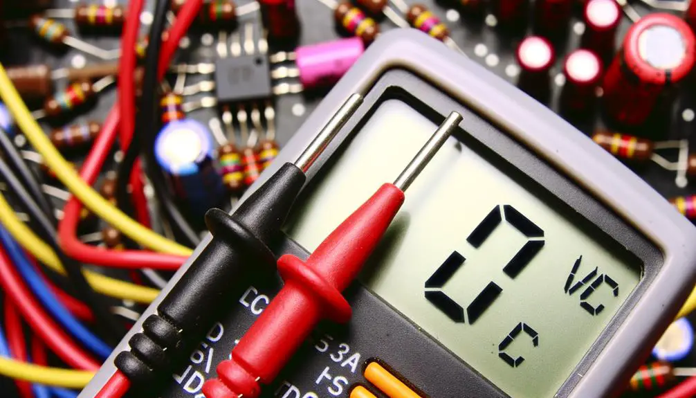
Accurate measurement of DC voltage, denoted by the symbol 'V' with a straight line above a dashed line, is crucial for diagnosing and troubleshooting various electrical and electronic circuits.
DC voltage, representing a constant and unidirectional flow of electric charge, is critical in applications ranging from battery-powered devices to intricate electronic systems.
Precise measurement facilitates the identification of component failures, improper connections, and potential short circuits. Moreover, it verifies the correct operation of devices by comparing voltage levels against specified tolerances.
Understanding DC voltage values is essential for maintaining system integrity, optimizing performance, and ensuring safety.
Consequently, proficiency in measuring DC voltage with a multimeter is an indispensable skill for technicians and engineers in the field.
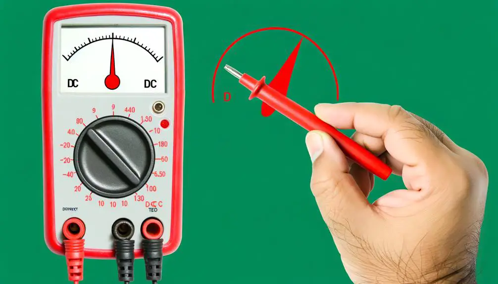
Identifying DC Voltage Symbol
Identifying the DC voltage symbol on a multimeter is essential for accurate measurements and device functionality. Typically represented by a 'V' with a straight line above it, this symbol indicates the multimeter setting for DC voltage.
Effective visual identification and correct dial settings guarantee precise readings and prevent potential damage to the equipment.
Common DC Voltage Symbol
The common DC voltage symbol on a multimeter is often denoted by a capital 'V' with one or more straight lines above it, sometimes accompanied by a dashed line. This symbol is essential for differentiating between DC and AC voltage measurements. Below, a table illustrates different representations of the DC voltage symbol for clarity:
| Symbol | Description | Example Multimeters |
|---|---|---|
| V⎓ | DC Voltage | Fluke, Klein Tools |
| V- – – – – | DC Voltage with dashes | Extech, Amprobe |
| V⎓⎓ | Double Straight Lines | Brymen, Greenlee |
| V⎓⎓⎓⎓⎓ | Multiple Lines | Keysight, UNI-T |
Understanding these symbols guarantees accurate measurement and prevents errors during electrical diagnostics.
Multimeter Dial Settings
Exploring the multimeter dial settings is essential for accurately identifying the DC voltage symbol and ensuring precise electrical measurements.
The dial on a multimeter typically includes various symbols and ranges, each representing distinct measurement capabilities.
The DC voltage symbol, often denoted by a solid line above a dashed line (V̅), signifies the direct current voltage mode. Properly setting the dial to this symbol is critical for obtaining valid measurements when evaluating DC circuits.
Incorrect dial settings can result in erroneous readings or potential harm to the device.
Moreover, ensuring the multimeter is set to the appropriate DC voltage range enhances measurement accuracy and instrument longevity, emphasizing the importance of familiarizing oneself with the multimeter's operational interface.
Visual Identification Tips
Recognizing the DC voltage symbol on a multimeter dial requires understanding its visual representation, typically depicted by a 'V' followed by a straight line over a dashed line (V̅). This symbol indicates direct current (DC) voltage measurement.
The straight line indicates a constant voltage, while the dashed line represents a non-varying, steady state. When identifying this symbol, make sure the multimeter is set accurately to prevent erroneous readings.
The symbol's precise placement on the dial varies by manufacturer, but its fundamental design remains consistent. Familiarity with this symbol is essential for accurate voltage measurement, especially in applications requiring differentiation between AC (alternating current) and DC voltage.
Proper identification guarantees reliable diagnostics and enhances measurement accuracy.
Different Multimeter Symbols
To effectively utilize a multimeter, it is important to comprehend the various symbols it employs, particularly those indicating different voltage types and ranges.
The common multimeter symbols, such as V for voltage, Ω for resistance, and A for current, are essential for accurate measurement and diagnostics.
Additionally, understanding the specific symbols for DC and AC voltage, typically represented as V⎓ and V~, respectively, can greatly enhance measurement precision and efficiency.
Common Multimeter Symbols
Understanding the various symbols on a multimeter is essential for accurate measurement and diagnosis of electrical circuits. Multimeters are equipped with a range of symbols that denote different measurement functions, ensuring precision and reliability in testing. Key symbols include V with a straight line for DC Voltage, V with a wavy line for AC Voltage, Ω for resistance, and A for current. Each symbol is a navigational aid, directing the user to the correct measurement setting and ensuring accurate data collection.
| Symbol | Measurement Type | Description |
|---|---|---|
| V― | DC Voltage | Measures direct current voltage |
| V~ | AC Voltage | Measures alternating current voltage |
| Ω | Resistance | Measures electrical resistance |
| A | Current | Measures electrical current |
Correct interpretation of these symbols is vital for effective multimeter usage.
Understanding Voltage Indicators
Voltage indicators on a multimeter, represented by specific symbols, are necessary for distinguishing between measurements of direct current (DC) and alternating current (AC) voltages.
The DC voltage symbol typically comprises a straight line with a dashed line beneath it, signifying a unidirectional flow of electric charge. Conversely, the AC voltage symbol is denoted by a sine wave, indicating the periodic variation in magnitude and direction.
Understanding these symbols is essential for accurate voltage measurements, as incorrect interpretation can lead to erroneous readings and potential equipment damage.
Additionally, advanced multimeters may feature additional icons, such as a "V" with a tilde (~) for AC and a "V" with a solid line and dashed line for DC, enhancing user clarity and precision.
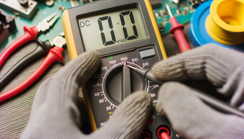
Steps to Measure DC Voltage
Accurately measuring DC voltage with a multimeter requires adherence to a systematic procedure to guarantee precise readings and user safety. Follow these steps meticulously:
- Select the DC Voltage Setting: Turn the dial to the DC voltage symbol (usually denoted as 'V' with a straight line and dashed line beneath it).
- Connect the Probes: Insert the black probe into the COM port and the red probe into the VΩmA port on the multimeter.
- Attach Probes to Circuit: Place the black probe on the ground or negative terminal and the red probe on the positive terminal of the circuit.
- Read the Display: Observe the multimeter display for the voltage reading, ensuring the value stabilizes before recording.
This method guarantees accuracy and maintains safety in electrical measurements.
Common Multimeter Settings
Understanding the common settings on a multimeter is essential for accurate measurement and diagnostics.
Key settings include:
- Voltage measurement modes, encompassing both AC and DC.
- Resistance and continuity tests.
Mastery of these functions enhances the utility and effectiveness of the multimeter in various electrical assessments.
Voltage Measurement Modes
Multimeters typically offer various settings for measuring voltage, including direct current (DC) voltage and alternating current (AC) voltage, to accommodate different electrical testing needs. These measurement modes are essential for accurately diagnosing and troubleshooting electrical circuits.
Common multimeter settings for voltage measurement include:
- DC Voltage (V–): Used for measuring the voltage in direct current circuits, such as batteries or DC power supplies.
- AC Voltage (V~): Utilized for alternating current circuits, such as household electrical outlets.
- Auto-ranging: Automatically selects the appropriate measurement range, simplifying the process for the user.
- Manual-ranging: Allows the user to manually select the measurement range, offering greater control and specificity.
Understanding these modes enables precise and effective voltage measurements, critical for ensuring electrical system integrity.
Resistance and Continuity
Resistance and continuity measurement modes on a multimeter are essential for diagnosing circuit integrity and identifying potential faults. Resistance mode, symbolized by the Greek letter Omega (Ω), quantifies the opposition to current flow within a circuit, aiding in the evaluation of components such as resistors, wires, and connections.
Continuity mode, often denoted by a diode symbol or sound wave icon, tests for unbroken electrical pathways, emitting an audible alert if a low-resistance path exists. These functions are pivotal for detecting open circuits, short circuits, and verifying proper solder joints.
Utilizing these settings effectively guarantees accurate troubleshooting and maintenance, fostering reliable and efficient electrical system performance. Understanding these features enhances diagnostic precision and circuit assessment capabilities.
Avoiding Common Mistakes
A vital aspect of accurately measuring DC voltage with a multimeter involves guaranteeing correct probe placement and dial settings to avoid erroneous readings. Common mistakes can lead to inaccurate measurements or even damage to the multimeter.
To mitigate these errors, consider the following:
- Probe Placement: Confirm the red probe is connected to the VΩmA port and the black probe to the COM port.
- Dial Setting: Set the dial to the appropriate DC voltage range, typically denoted by a 'V' with a straight line.
- Polarity Awareness: Connect the probes to the circuit, observing the correct polarity to avoid reversed readings.
- Meter Functionality: Verify the multimeter is functioning correctly before taking measurements to guarantee accuracy.
These steps are essential in achieving reliable and accurate voltage readings.
Tips for Accurate Readings
Building upon the foundation of avoiding common mistakes, achieving precise DC voltage measurements necessitates adherence to several best practices.
First, verify the multimeter's probes are in good condition and properly connected to the appropriate ports. Use the correct DC voltage range to avoid overloading the meter. Zero the meter before taking readings to eliminate any residual offset.
Minimize electromagnetic interference by keeping the probes and wires away from high-frequency sources. Consistently maintain a steady hand or use probe clips to guarantee stable contact with the measurement points.
Maintaining Your Multimeter
Proper maintenance of your multimeter is crucial to guarantee its longevity and consistent accuracy. Analyzing the key aspects of maintenance involves focusing on several critical procedures.
- Regular Calibration: Conduct periodic calibration of the device to maintain measurement precision.
- Battery Management: Replace batteries promptly to avoid leakage and ensure best functionality.
- Probe Inspection: Regularly examine probes for wear and tear, making sure they are clean and properly connected.
- Storage Conditions: Keep the multimeter in a dry, dust-free environment to prevent moisture-induced corrosion and contamination.
Adhering to these maintenance protocols will not only extend the lifespan of your multimeter but also enhance the reliability of its measurements, making sure it performs at peak efficiency.
Advanced Multimeter Features
While maintaining your multimeter guarantees its longevity, understanding its advanced features can greatly enhance its utility and efficiency in complex measurements.
Modern multimeters come equipped with functionalities such as True RMS (Root Mean Square) for accurate AC voltage measurements, even with non-sinusoidal waveforms.
Auto-ranging capabilities simplify the measurement process by automatically selecting the appropriate range, eliminating manual adjustments.
Additionally, dual display screens allow simultaneous readings of two different parameters, enhancing multitasking efficiency.
Data logging and Bluetooth connectivity facilitate real-time monitoring and data transfer to computing devices for further analysis.
Finally, low impedance mode (LoZ) minimizes ghost voltages, ensuring more precise readings.
Mastery of these features transforms basic measurement tasks into highly accurate and efficient diagnostic processes.
Conclusion
To sum up, mastering the identification and measurement of DC voltage using a multimeter is essential for accurate diagnostics in electrical engineering and related fields. The complexity and variety of multimeter symbols can initially seem overwhelming; however, with systematic study and adherence to proper measurement protocols, precision can be achieved.
Despite potential skepticism regarding the necessity of such detailed understanding, proficiency in these foundational concepts is crucial for ensuring reliable and accurate electrical measurements, ultimately enhancing technical competence and operational safety.