What Is the Circuit Symbol for a Capacitor and Its Variations?
A capacitor's circuit symbol is pivotal for accurate electrical schematics. The basic symbol comprises two parallel lines representing conductive plates separated by a dielectric.
A polarized capacitor symbol indicates the positive terminal with a plus sign, crucial for correct orientation and preventing damage. Variable capacitors feature a diagonal arrow, indicating adjustable capacitance for tuning frequencies.
Electrolytic capacitors also denote positive and negative terminals, emphasizing proper orientation to avoid failure. Ceramic capacitors, non-polarized, are preferred for high-frequency applications due to their stability.
Understanding these symbols guarantees precise circuit design and functionality. Explore further to deepen your grasp of these components.
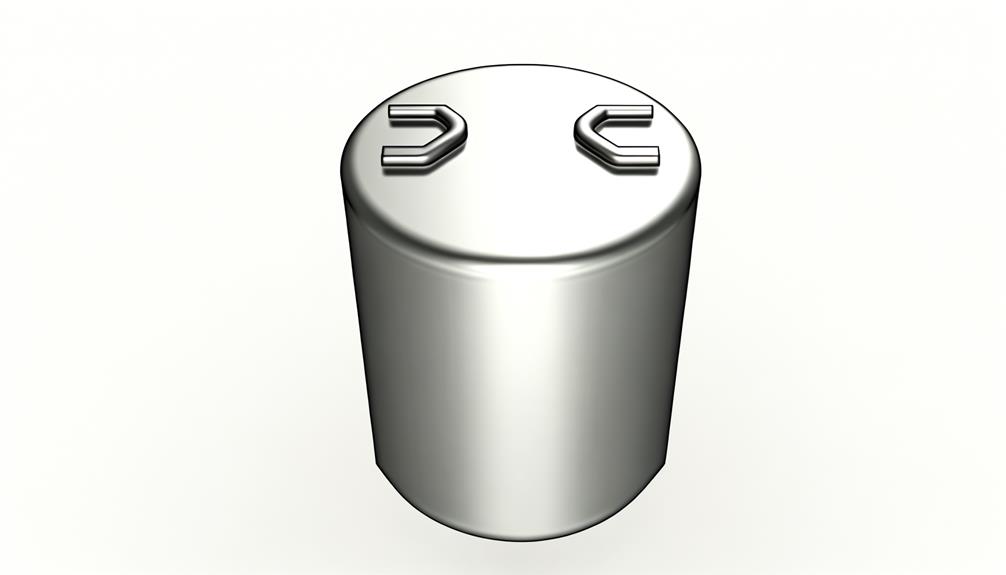
Key Takeaways
- The basic capacitor symbol consists of two parallel lines representing the conductive plates.
- A polarized capacitor symbol includes a plus sign to indicate the positive terminal.
- A variable capacitor symbol features a diagonal arrow indicating adjustability.
- Electrolytic capacitors are marked with positive and negative terminals for proper orientation.
- Ceramic capacitor symbols are non-polarized and suitable for high-frequency applications.
Basic Capacitor Symbol

A basic capacitor symbol is represented by two parallel lines, indicating the two conductive plates separated by a dielectric material. This graphical representation is fundamental in electrical schematics, providing a clear and unambiguous visual cue for the inclusion of a capacitor in the circuit.
The parallel lines symbolize the capacitive plates, each line connected to a terminal. The dielectric material between the plates, essential for the capacitor's function, is implied but not depicted. This symbolism guarantees ease of identification and understanding for engineers and technicians, facilitating efficient circuit design and analysis.
The simplicity of the basic capacitor symbol underscores its foundational role in a wide array of electronic applications, from filtering to energy storage.
Polarized Capacitor Symbol
Polarized capacitors, typically denoted by distinct symbols incorporating a plus sign to indicate the positive terminal, are necessary in applications requiring unidirectional voltage. Unlike non-polarized capacitors, polarized types, such as electrolytic capacitors, must be connected correctly to avoid damage or failure. The symbol for a polarized capacitor consists of two parallel lines, with one line often curved and accompanied by a plus sign denoting the anode. This differentiation is important for circuits with DC bias.
| Type | Symbol |
|---|---|
| Electrolytic |  |
| Tantalum |  |
| Polymer |  |
| Supercapacitor |  |
| Aluminum Electrolytic |  |
Understanding these symbols guarantees proper capacitor selection and circuit functionality, preventing potential malfunctions.
Variable Capacitor Symbol
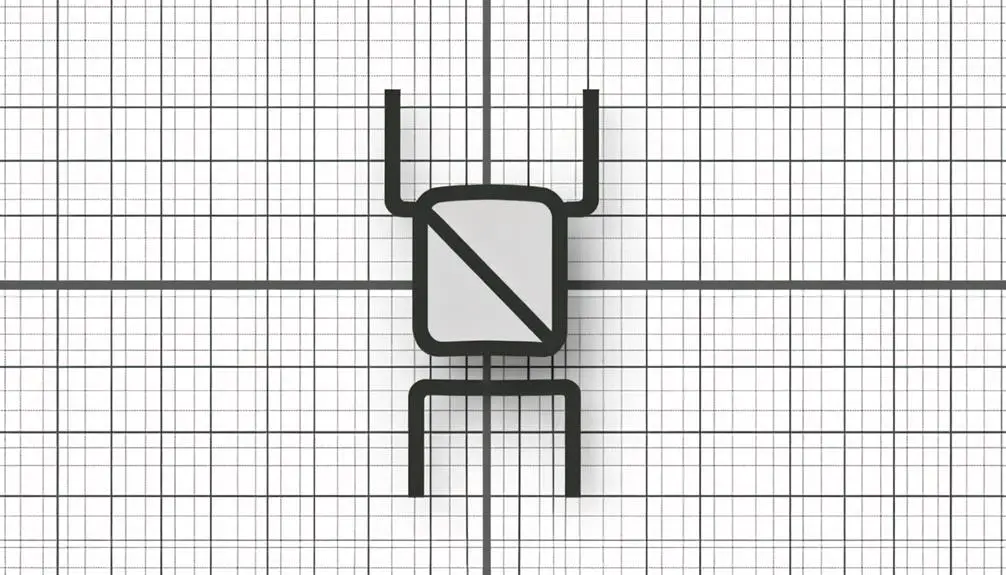
Variable capacitors, unlike their fixed counterparts, allow for the adjustment of capacitance values within a circuit, making them indispensable in applications such as tuning radios and oscillators.
The circuit symbol for a variable capacitor typically consists of the standard capacitor symbol with an added diagonal arrow through it, signifying its adjustable nature. This symbol effectively communicates the component's ability to vary its capacitance.
Variable capacitors can be mechanically adjusted via a rotating knob or screw mechanism, changing the distance between plates or the overlapping surface area. These capacitors are vital for fine-tuning frequencies and achieving best circuit performance.
Understanding the symbol and functionality of variable capacitors is essential for designing and troubleshooting frequency-dependent electronic systems.
Electrolytic Capacitor Symbol
Electrolytic capacitors, often utilized in power supply circuits, are distinguished by their polarity and higher capacitance values compared to other types of capacitors. The schematic symbol for an electrolytic capacitor features two parallel lines, where one is straight and the other is curved or shorter. This differentiation signifies the capacitor's polarity, with the straight line indicating the positive terminal (anode) and the curved or shorter line representing the negative terminal (cathode).
It is vital to observe this polarity during installation, as incorrect connections can lead to capacitor failure or damage. Electrolytic capacitors are typically marked with a clear indication of the positive and negative leads, ensuring proper orientation in the circuit design.
Ceramic Capacitor Symbol

The ceramic capacitor symbol in circuit diagrams is represented by two parallel lines, both of which are straight, indicating the non-polarized nature of this component. This symbol is pivotal for electronic schematics due to its simplicity and ability to denote a capacitor that can be inserted in any orientation.
Key features of the ceramic capacitor symbol include:
- Non-polarized design: Allows for installation in either direction.
- High-frequency performance: Suitable for applications requiring minimal inductance.
- Compact size: Ideal for space-constrained designs.
- Variety of capacitance values: Suits diverse electronic applications.
- Stability and reliability: Guarantees consistent performance over time.
Understanding this symbol aids in accurate circuit design and effective troubleshooting, making it indispensable for engineers and technicians alike.
Tantalum Capacitor Symbol
The symbol for a tantalum capacitor typically includes a distinct marking to indicate polarity, which is essential for preventing circuit malfunctions.
Its design characteristics often feature a plus sign (+) near the positive terminal, differentiating it from non-polarized capacitor symbols.
These capacitors are widely utilized in applications requiring high stability and low leakage currents, such as in filtering and timing circuits.
Symbol Design Characteristics
Tantalum capacitor symbols are typically represented by a small rectangular shape with polarity markings to indicate the anode and cathode. These symbols are designed to provide clear visual cues for proper component orientation in circuits.
Key design characteristics include:
- Rectangular Shape: Simplifies identification in circuit diagrams.
- Polarity Indication: Guarantees correct alignment, essential for functionality.
- Anode Marking: Usually depicted with a plus sign (+) or a distinct line.
- Cathode Marking: Often indicated by a minus sign (-) or absence of marking.
- Standardization: Adheres to industry standards for consistency.
These attributes enable engineers to quickly and accurately interpret circuit schematics, ensuring reliable assembly and performance of electronic systems.
Understanding these design characteristics is fundamental for proficient circuit design and troubleshooting.
Polarity Identification Importance
Precisely marked polarity on tantalum capacitor symbols is essential for preventing damage and ensuring high-quality performance in electronic circuits. Tantalum capacitors are inherently polarized, meaning they have distinct positive (anode) and negative (cathode) terminals.
Incorrectly connecting these capacitors can lead to catastrophic failures, including short circuits, leakage, or even capacitor explosion. The schematic symbol typically includes a clear indication of polarity, often with a plus (+) sign denoting the anode.
Accurate polarity identification allows for proper integration within the circuit, optimizing functionality and reliability. The significance of this is vital in applications requiring precise capacitance values and stable performance, making it indispensable for engineers to heed polarity markings meticulously.
Applications in Circuitry
Widely employed in various electronic applications, tantalum capacitors are favored for their high capacitance per volume and excellent stability. These capacitors are integral in ensuring efficient circuit performance, particularly in environments demanding reliability and compactness.
Key applications include:
- Power Supply Filtering: Tantalum capacitors smooth ripple voltage.
- Decoupling: Isolating different parts of a circuit to minimize noise.
- Timing Circuits: Providing precise timing intervals in oscillators and clocks.
- Signal Coupling: Transmitting AC signals while blocking DC components.
- Bypass Capacitors: Stabilizing voltage supplies in integrated circuits.
Their symbol in circuit diagrams is characterized by a polarity marking, ensuring correct orientation. This specificity in application underscores the critical role of tantalum capacitors in advanced electronics.
Decoding Capacitor Labels
Understanding capacitor labels is crucial for accurately identifying their specifications and guaranteeing proper integration into electronic circuits. Capacitor labels typically include capacitance value, voltage rating, tolerance, and temperature coefficient.
The capacitance value, often in microfarads (μF), nanofarads (nF), or picofarads (pF), indicates the amount of charge a capacitor can store. Voltage rating specifies the maximum voltage the capacitor can handle without risk of breakdown.
Tolerance indicates the permissible deviation from the nominal capacitance, commonly expressed as a percentage. The temperature coefficient denotes how the capacitance value changes with temperature, annotated in parts per million per degree Celsius (ppm/°C).
Properly decoding these labels guarantees compatibility and reliability in circuit design and performance.
Capacitor Symbols in Schematics
In schematic diagrams, capacitors are represented by distinct symbols that convey their type and function.
Basic capacitors are depicted by two parallel lines, while polarized capacitors incorporate a '+' sign to indicate polarity.
Variable capacitors are illustrated with an arrow intersecting the parallel lines, signifying adjustability.
Basic Capacitor Symbols
Capacitor symbols in schematics are necessary for accurately representing the component's function and properties within an electrical circuit. These symbols convey critical information that facilitates the design, analysis, and troubleshooting of electronic systems. Basic capacitor symbols are standardized to guarantee consistency and clarity.
Key attributes of basic capacitor symbols include:
- Two parallel lines: Represent the capacitor's plates.
- Straight lines: Indicate non-polarized capacitors.
- Curved line: Sometimes used for one plate in simplified symbols.
- Labeling: Often includes capacitance value (e.g., µF, pF).
- Associated symbols: May include variable capacitors, denoted by an arrow through the symbol.
Understanding these symbols is fundamental for interpreting and creating schematics, ensuring precise communication of circuit designs.
Polarized Capacitor Symbols
While basic capacitor symbols denote general characteristics, polarized capacitor symbols provide additional details to indicate the orientation and specific type of the capacitor within the circuit. These symbols are vital for electrolytic and tantalum capacitors, which have distinct positive and negative terminals.
In schematic diagrams, polarized capacitors are typically represented with a straight line (positive terminal) and a curved line (negative terminal) or a plus and minus sign. Proper orientation is essential since incorrect installation can lead to component failure or circuit malfunction.
Additionally, polarized capacitors are often marked with a shaded or colored band to denote polarity. Understanding these symbols ensures accurate circuit design and operational integrity, especially in applications requiring precise voltage regulation and filtering.
Variable Capacitor Symbols
Variable capacitor symbols in schematic diagrams are fundamental for denoting adjustable capacitance components, which allow for fine-tuning and calibration in various electronic circuits. These components are pivotal in applications such as oscillators, filters, and tuning circuits. The symbol typically consists of a standard capacitor symbol with an arrow passing through it, indicating variability.
Key features include:
- Adjustability: Facilitates precise tuning of circuit parameters.
- Arrow Indicator: Denotes the variability of the capacitance.
- Dual Plates with Arrow: Represents the adjustable nature of the plates.
- Schematic Clarity: Ensures clear representation of variable components.
- Versatility: Used in RF circuits, audio equipment, and more.
Understanding these symbols is vital for designing and interpreting complex electronic schematics accurately.
Conclusion
The representation of capacitors in circuit diagrams employs various symbols to denote different types, each with distinct characteristics.
Importantly, polarized capacitors are essential in applications requiring directional current flow, with electrolytic capacitors being prevalently used due to their high capacitance values.
It is noteworthy that the global market for capacitors is projected to reach $30 billion by 2025, highlighting their essential role in modern electronics.
Accurate interpretation of these symbols is crucial for electrical engineers and technicians in designing and troubleshooting circuits.


