How to Identify and Draw the Circuit Breaker Symbol in Electrical Circuits
In electrical circuit diagrams, circuit breaker symbols are standardized to represent different types of breakers such as miniature circuit breakers (MCBs), molded case circuit breakers (MCCBs), and residual current circuit breakers (RCCBs). These symbols indicate attributes like voltage rating, interrupting capacity, and trip mechanisms.
Understanding these symbols is crucial for designing and troubleshooting electrical systems. Common representations include a rectangle with a diagonal line for MCBs and additional notations for specialized breakers.
Properly labeled diagrams enhance communication and guarantee the safety and reliability of electrical circuits. To understand these symbols more extensively, there is further detailed information available.
Key Takeaways
- Circuit breaker symbols represent various types, including MCBs, MCCBs, and RCCBs.
- Symbols indicate breaker traits like voltage rating, interrupting capacity, and trip mechanisms.
- Accurate labeling of circuit breaker symbols is crucial for clear circuit diagram interpretation.
- Standard symbols facilitate quick identification and understanding of breaker types in diagrams.
- Mastery of circuit breaker symbols enhances troubleshooting and design accuracy for electrical circuits.
Understanding Circuit Diagrams
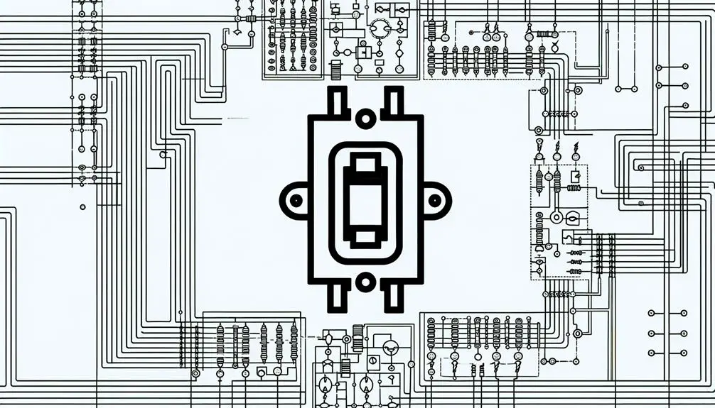
Understanding circuit diagrams is essential for anyone involved in electrical engineering, as these graphical representations detail the connections and components within an electrical system with precise symbols and standardized notations.
Circuit diagrams, also known as schematic diagrams, utilize industry-standard symbols to represent various electrical components such as resistors, capacitors, inductors, and switches. The standardized notations and layout guarantee clear communication and interpretation across different stakeholders, including engineers, technicians, and designers.
Each symbol's orientation and connection delineate the functional relationship and operational flow within the circuit. Mastery of reading and creating circuit diagrams is crucial for designing, diagnosing, and troubleshooting electrical systems, ensuring accuracy and efficiency in the development and maintenance of electrical infrastructure.
Understanding these diagrams is fundamental to proficient electrical engineering practices.
Importance of Circuit Breakers
Circuit breakers serve a critical function in electrical systems by preventing electrical overloads, thereby mitigating potential fire hazards and system failures.
By automatically interrupting the current flow in the event of a fault condition, they enhance safety measures for both residential and industrial environments.
Additionally, circuit breakers protect sensitive electrical equipment from damage caused by surges and short circuits, ensuring operational reliability and longevity.
Prevents Electrical Overloads
To mitigate the risks of electrical overloads, circuit breakers serve as critical protective devices by interrupting the current flow when excessive load conditions are detected. These devices are engineered to respond to overcurrent situations, which can occur due to short circuits or sustained high demand on the electrical system.
Utilizing a mechanical switch mechanism, circuit breakers disconnect the electrical circuit, thereby preventing potential damage to wiring, equipment, and connected devices. The internal trip mechanism is calibrated to specific amperage ratings, ensuring that the breaker activates precisely at the threshold where overheating and damage would otherwise occur.
Such precision in design and operation underscores the crucial role of circuit breakers in maintaining electrical system integrity and preventing hazardous overload conditions.
Enhances Safety Measures
The implementation of circuit breakers is crucial in enhancing safety measures within electrical systems by providing reliable interruption of current flow during fault conditions. These devices are engineered to detect anomalies such as overcurrents, short circuits, and ground faults, which could otherwise lead to hazardous situations including electrical fires or equipment damage.
By automatically disengaging the electrical circuit upon identification of these irregularities, circuit breakers prevent the flow of excessive current, thereby mitigating risks associated with electrical faults. This interruption capability ensures that the electrical system operates within safe parameters, safeguarding both infrastructure and personnel.
Additionally, advanced circuit breakers incorporate features like arc fault detection and ground fault interruption, further elevating the safety protocols embedded within modern electrical installations.
Protects Electrical Equipment
By interrupting the flow of current during fault conditions, circuit breakers not only enhance safety measures but also play a pivotal role in protecting sensitive electrical equipment from potential damage caused by overcurrents, short circuits, and other electrical anomalies.
This critical function is achieved through the rapid opening of contacts within the breaker, which isolates the faulty section of the circuit. The precision in tripping characteristics ensures minimal disruption to operational continuity while safeguarding components such as transformers, motors, and control systems.
Additionally, the integration of advanced technologies, including arc-fault detection and ground-fault protection, enhances a circuit breaker's ability to mitigate risks, thereby maintaining the integrity and longevity of electrical infrastructure.
Basic Electrical Symbols
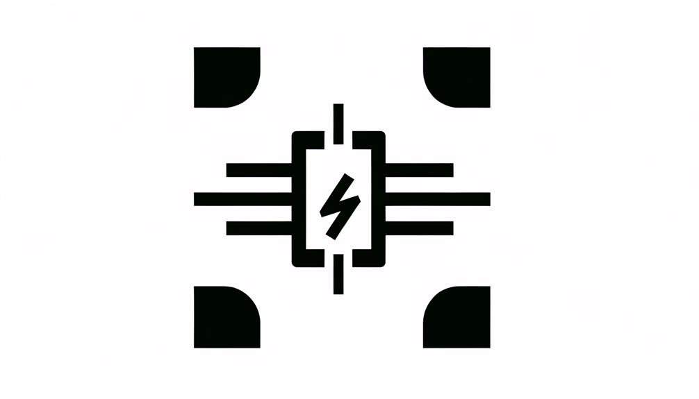
Understanding basic electrical symbols is essential for accurately interpreting circuit diagrams, facilitating efficient communication among professionals.
Common electrical symbols, such as resistors, capacitors, and circuit breakers, serve as standardized representations of components within an electrical system.
Mastery of these symbols guarantees precise construction, troubleshooting, and maintenance of electrical circuits.
Common Electrical Symbols
Electrical schematics utilize standardized symbols to represent various components, with common symbols including resistors, capacitors, diodes, and circuit breakers. These symbols, governed by standards such as IEEE and IEC, guarantee uniformity and comprehensibility across different schematics.
A resistor is typically denoted by a zigzag line, indicating resistance to current flow. Capacitors, which store electrical energy, are depicted as two parallel lines for non-polarized types or one straight and one curved line for polarized types.
Diodes, allowing current flow in one direction, are represented by a triangle pointing to a line. Circuit breakers, essential for safety, are symbolized by a rectangle with a line through it, signifying the interruptive capability. Mastery of these symbols is necessary for accurate circuit design and analysis.
Interpreting Circuit Diagrams
Interpreting circuit diagrams necessitates a thorough understanding of basic electrical symbols to accurately analyze and troubleshoot electrical systems. These symbols represent various electrical components such as resistors, capacitors, inductors, diodes, and transistors, each denoted by standardized icons.
Circuit breakers, indicated by a simple rectangle with a line bisecting it, are critical for understanding protection mechanisms within the system. Proper interpretation involves recognizing connections, power sources, and the flow of current, which are depicted by lines and arrows.
Mastery of these symbols enables the identification of circuit functionalities, potential faults, and necessary repairs. Knowledge of the International Electrotechnical Commission (IEC) and American National Standards Institute (ANSI) standards is essential for ensuring consistency and accuracy in diagram interpretation.
Anatomy of a Circuit Breaker
A circuit breaker comprises several critical components, including the frame, operating mechanism, contacts, arc extinguisher, and trip unit, each serving a specific function to guarantee the safe interruption of electrical current.
The frame provides structural integrity and houses other components. The operating mechanism is responsible for opening and closing the contacts, which physically separate to interrupt the current flow.
The arc extinguisher, often a series of metal plates or a vacuum chamber, dissipates the electrical arc generated when contacts open. Finally, the trip unit detects overcurrent conditions and actuates the operating mechanism to prevent electrical faults.
Together, these components ensure the circuit breaker effectively mitigates risks associated with electrical overloads and short circuits.
Common Circuit Breaker Symbols
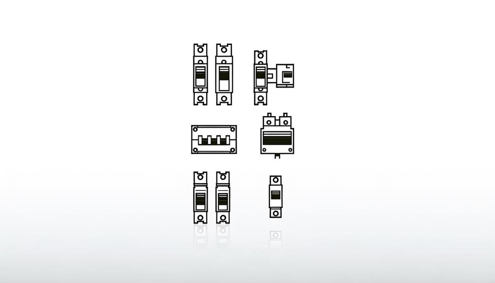
In the context of electrical schematics, common circuit breaker symbols are vital for conveying complex information succinctly.
This section will outline standard breaker icons, provide a symbol representation guide, and offer diagram labeling tips to guarantee clarity and uniformity.
Understanding these elements is pivotal for accurate interpretation and effective communication within electrical engineering documentation.
Standard Breaker Icons
Standard breaker icons, universally recognized symbols in electrical schematics, facilitate the identification and understanding of various types of circuit breakers. These icons represent devices that interrupt the flow of current in an electrical circuit to prevent damage and maintain safety.
For instance, the standard symbol for a single-pole circuit breaker is a simple rectangle with a diagonal line, denoting one interrupting element. Double-pole breakers, essential for higher voltage applications, are depicted with two interconnected rectangles, each with a diagonal line.
Ground fault circuit interrupters (GFCI) are indicated by a rectangle with a 'T' symbol, signifying their specialized function. These standardized icons are vital for maintaining consistency and clarity in electrical diagrams, aiding in efficient communication among professionals.
Symbol Representation Guide
Understanding the full array of circuit breaker symbols is crucial for the precise interpretation and development of electrical schematics in professional settings. These symbols offer visual shorthand for various kinds of circuit breakers, including miniature circuit breakers (MCBs), molded case circuit breakers (MCCBs), and residual current circuit breakers (RCCBs).
Each symbol is standardized to convey specific traits, such as voltage rating, interrupting capacity, and trip mechanisms. For example, an MCB might be illustrated with a simple rectangle interrupted by a diagonal line, while an MCCB might incorporate additional lines to indicate higher capacity. These representations guarantee that all professionals can promptly identify the type and specifications of circuit protection devices, promoting safety and efficiency in electrical design and maintenance.
Diagram Labeling Tips
Accurate diagram labeling of circuit breaker symbols is essential for ensuring clear communication and precise interpretation in electrical schematics. Proper labeling involves using standardized symbols, such as the ANSI or IEC symbols, to represent various types of circuit breakers.
Each symbol must be annotated with specific attributes, including rated current (In), breaking capacity (Icu), and tripping characteristics (B, C, D curves). Labels should be placed adjacent to the symbols, minimizing ambiguity by maintaining consistent orientation and spacing.
Additionally, color codes or line types may be employed to distinguish between different circuit functions. Adhering to these labeling conventions facilitates troubleshooting, maintenance, and compliance with regulatory standards, thereby enhancing the reliability and safety of electrical installations.
How to Read the Symbol
In electrical schematics, the circuit breaker symbol is typically represented by a rectangle with a line intersecting it, which signifies a switch that can interrupt the flow of current. This symbol is vital for identifying the location and function of the circuit breaker within the electrical circuit.
The rectangle usually denotes the housing of the breaker, while the intersecting line indicates the mechanical switch. Additional annotations often include ratings such as voltage, current, and interrupting capacity, which are essential for guaranteeing compatibility and safety.
Understanding these symbols and annotations allows for precise interpretation of circuit diagrams, facilitating accurate design, troubleshooting, and maintenance of electrical systems. Proper reading ensures adherence to electrical standards and best system performance.
Types of Circuit Breakers
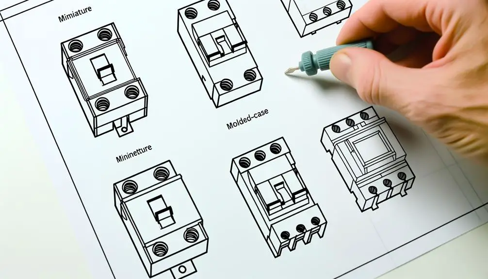
Circuit breakers come in various types, each tailored to specific applications and operating conditions, including thermal-magnetic, hydraulic-magnetic, and electronic models.
Thermal-magnetic circuit breakers utilize a bimetallic strip and electromagnet to respond to overcurrent conditions, offering protection against both short circuits and prolonged overloads.
Hydraulic-magnetic circuit breakers employ a hydraulic mechanism to delay tripping, ensuring stability under transient surges while providing precise protection.
Electronic circuit breakers leverage advanced sensing and microprocessor technology to detect abnormal currents with high accuracy, often incorporating adjustable trip settings and communication capabilities for integration into smart systems.
Each type serves distinct roles, fulfilling critical safety and reliability requirements in diverse electrical infrastructures, from residential setups to industrial power systems.
Circuit Breaker Functions
Understanding the functions of a circuit breaker is essential for ensuring the safety and reliability of electrical systems. These devices are engineered to detect and interrupt abnormal current flows, thereby preventing damage to equipment and reducing fire hazards.
Circuit breakers perform several critical functions, which include:
- Overcurrent Protection: They interrupt excessive currents resulting from overloads or short circuits, thereby safeguarding electrical infrastructure.
- Isolation: Circuit breakers provide a means to disconnect electrical circuits for maintenance or emergency purposes, ensuring safe working conditions.
- Fault Detection: By monitoring current flow, circuit breakers can identify faults such as line-to-ground faults or arc faults, initiating a trip mechanism to halt the flow of electricity.
These functions collectively enhance the operational integrity of electrical systems.
Integration in Electrical Systems

How seamlessly circuit breakers are integrated into electrical systems directly impacts their overall efficiency and safety. Precise integration necessitates understanding system load requirements, circuit design, and breaker specifications. Key factors influencing integration include current rating, interrupting capacity, and physical configuration. Below is a table that delineates these parameters:
| Parameter | Description | Importance |
|---|---|---|
| Current Rating | The maximum current the breaker can carry | Ensures compatibility with system load |
| Interrupting Capacity | The maximum fault current the breaker can interrupt | Prevents system damage during fault conditions |
| Physical Configuration | The size and mounting type of the breaker | Facilitates ease of installation and replacement |
Understanding these elements aids in optimizing system reliability and minimizing downtime.
Safety Considerations
Securing the proper integration of circuit breakers into electrical systems also necessitates a thorough consideration of safety protocols to mitigate risks associated with electrical faults.
The following three key safety considerations are essential:
- Overcurrent Protection: Circuit breakers must precisely match the system's load capacity to prevent overheating or potential fire hazards due to excessive current flow.
- Arc Fault Detection: Implementing arc fault circuit interrupters (AFCIs) can identify dangerous arcing conditions, reducing the risk of electrical fires.
- Ground Fault Protection: Ground fault circuit interrupters (GFCIs) should be employed in areas prone to moisture, such as bathrooms and kitchens, to shield against electrical shock hazards.
These measures guarantee robust safety mechanisms, preserving both system integrity and user safety.
Troubleshooting and Maintenance
Properly diagnosing and maintaining circuit breakers is paramount to guaranteeing the continual reliability and safety of electrical circuits. Regular inspection should include visual assessments for signs of wear, corrosion, or damage.
Utilize a multimeter to measure circuit continuity and confirm the breaker trips at its designated current threshold. Thermal imaging can detect overheating issues, indicative of excessive current load or poor connections.
Periodic testing under load conditions verifies operational integrity. Replace any breakers exhibiting delayed trip times or inconsistent performance. Maintenance schedules should adhere to manufacturer guidelines and industry standards, such as those outlined by the IEEE.
Correctly maintained breakers mitigate the risk of electrical faults, enhancing system longevity and operational safety.
Conclusion
In the grand theater of electrical engineering, circuit breakers emerge as the unsung heroes, their symbols often overlooked yet pivotal.
These intricate devices, depicted through standardized icons, orchestrate the symphony of safety and functionality.
Mastering their representation guarantees robust circuit designs and mitigates catastrophic failures.
Consequently, the diligent scrutiny of circuit breaker symbols, akin to deciphering ancient hieroglyphics, fortifies the integrity of electrical systems, underscoring their indispensability in safeguarding modern infrastructure.


