Chemical Engineering Flow Diagram Symbols: Explain!
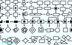
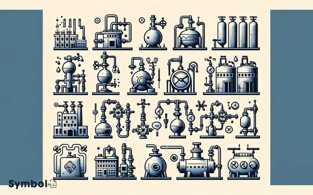
In chemical engineering, you rely on flow diagram symbols to visualize intricate processes. Straight lines indicate piping, with elbows and tees marking changes in direction and branch connections, respectively.
You’ll identify pumps and compressors by their unique symbols, critical for illustrating process flow. Vessels, tanks, and storage symbols denote containment, while heat exchangers and coolers are essential for temperature control.
Valve and actuator symbols help manage fluid flow, and instrumentation icons are key for control strategies.
Understanding symbols for reactors, mixers, and safety devices enhances your design and operational efficiency. Grasping these symbols transforms complex operations into detailed diagrams, paving the way for thorough analysis.
Key Takeaways
15 Symbols of Chemical Engineering Process Flow Diagram
| Symbol | Description | Example of Use |
|---|---|---|
| ⭘ | Pump | Used to represent a pump in P&IDs (Piping and Instrumentation Diagrams) |
| Δ | Heat Exchanger | Used to indicate a heat exchanger where heat is transferred between two fluids |
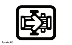
| → | Pipe | Represents the flow of fluid within pipes |
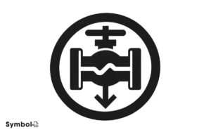
| ∇ | Valve | Symbolizes a valve to control fluid flow |
| ⬜ | Tank or Vessel | Indicates a storage tank or vessel |
| ⚙ | Compressor | Used to represent a compressor in a process flow diagram |
| ↔ | Flow Direction Indicator | Shows the direction of fluid flow in the system |
| ★ | Sensor or Transmitter | Symbolizes a sensor or transmitter for process measurements |
| ⧈ | Mixer | Used to denote a mixing operation of two or more substances |
| ⨁ | Filter | Represents a filter used to remove impurities from a fluid |
| ♻ | Recycling Loop | Indicates a recycling process within the system |
| Ψ | Cooling Tower | Used to symbolize a cooling tower in cooling processes |
| ℧ | Reactor | Represents a chemical reactor where reactions occur |
| ⇅ | Column | Indicates a distillation or fractionation column |
| ⚗ | Separator | Symbolizes a separator where different phases are separated |
Basic Piping and Connections
Understanding the symbols for basic piping and connections is essential for accurately interpreting and designing chemical engineering flow diagrams.
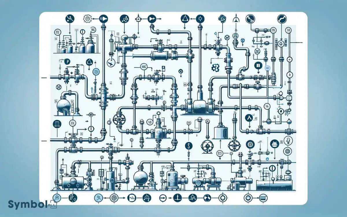
You’ll encounter a variety of symbols, each representing different types of pipes and connections. Straight lines indicate pipes, with their material and size specified by adjacent annotations.
Elbows, depicted by angled lines, show direction changes. Meanwhile, tees and crosses signify branch connections, essential for distributing or combining flows.
Flanges, illustrated with small circles or bolt heads, denote detachable joints, allowing for easy maintenance or modification.
It’s imperative you grasp these symbols’ meanings to comprehend the system’s layout, ensuring your designs or interpretations are both precise and efficient.
Mastery of these basics paves the way for understanding more complex components and systems in chemical engineering schematics.
Pumps and Compressors
You’ll now explore the symbols representing pumps and compressors in chemical engineering flow diagrams.
Understanding the variety of pump types and the core functions of compressors is essential for accurate diagram interpretation.

This section equips you with the knowledge to differentiate these symbols and their operational contexts effectively.
Understanding the symbols for pumps and compressors will enhance your ability to read and analyze chemical engineering flow diagrams. It is crucial to grasp the distinctions in how pumps and compressors are represented to interpret process flow accurately.
By mastering these symbols, you can identify the equipment and understand its function within the larger system.
Pump Types Overview
In the domain of chemical engineering, identifying the appropriate pump type is critical for optimizing fluid movement processes within systems.
You’ll encounter mainly two categories: centrifugal and positive displacement pumps.
Centrifugal pumps, favored for their simplicity and efficiency in moving large volumes, employ a rotating impeller to guarantee velocity to the fluid, converting this kinetic energy into flow or pressure.
On the other hand, positive displacement pumps guarantee a consistent flow, ideal for handling viscous fluids or when precise dosing is needed. They operate by trapping a fixed amount of fluid then forcing (displacing) that volume into the discharge pipe.
Each type has sub-varieties designed for specific applications, pressures, and fluid characteristics, making understanding their differences and operational principles paramount for selecting the right pump for your needs.
Compressor Function Essentials
Having explored pump types for fluid movement, let’s now focus on compressors, which play a pivotal role in manipulating gas pressure and volume in chemical engineering systems.
Unlike pumps, compressors are designed to work with gases, enhancing their pressure by reducing volume. This process is crucial for numerous applications, including refrigeration cycles, pneumatic equipment, and the synthesis of chemical products.
You’ll encounter various compressor types, each suited to specific applications based on efficiency, capacity, and the nature of the gas being compressed.
For instance, reciprocating compressors are chosen for high-pressure applications, while centrifugal compressors are preferred for larger, continuous flow needs.
Understanding these distinctions is essential for selecting the appropriate compressor for your system, ensuring peak performance and efficiency.
Vessels, Tanks, and Storage
Understanding the symbols for vessels, tanks, and storage is essential for interpreting and designing chemical engineering flow diagrams. These symbols represent the various types of containers used to hold gases, liquids, or solids.
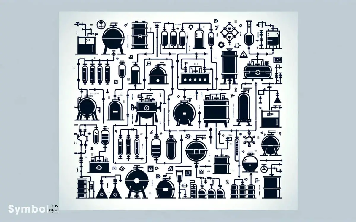
You’ll often encounter them in process flow diagrams (PFDs) and piping and instrumentation diagrams (P&IDs).
Each symbol is designed for quick recognition, aiding in the efficient communication and planning of chemical engineering processes.
Heat Exchangers and Coolers
Moving from storage solutions, let’s now examine heat exchangers and coolers, pivotal components for controlling process temperatures. You’ll find these symbols essential in chemical engineering flow diagrams.
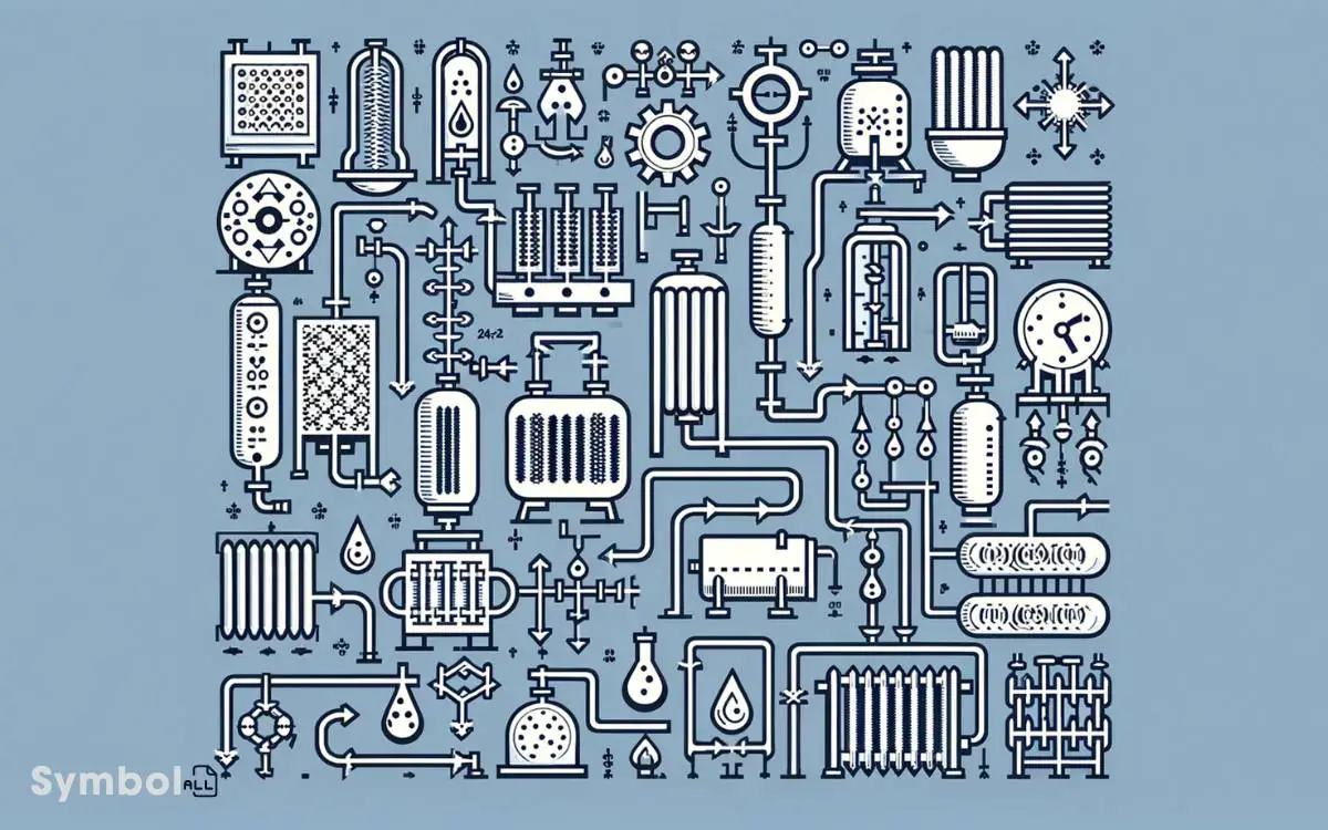
Heat exchangers facilitate energy transfer between two fluids without mixing them, vital for processes requiring precise temperature control. They’re represented by a set of parallel lines, sometimes with a shell or tube symbol to specify the type.
Coolers, on the other hand, remove heat from a fluid, lowering its temperature. The symbol typically involves a fan shape or a series of staggered lines, indicating air or water cooling methods, respectively.
Understanding these symbols allows you to grasp how process temperatures are managed, ensuring efficiency and safety in chemical engineering operations.
Valves and Actuators
You’ll find that understanding valve types is essential for effective fluid control in chemical engineering processes. Actuator functionality directly influences valve performance, dictating how well you can regulate flow and pressure.
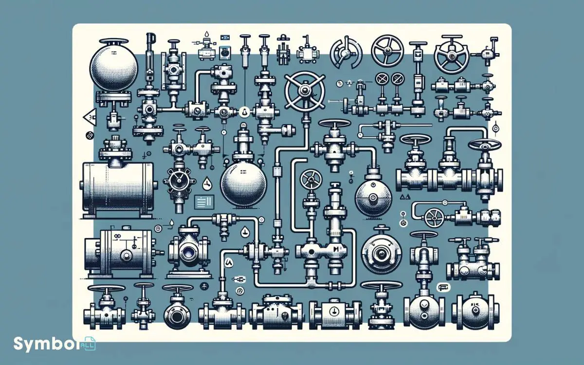
Selecting the appropriate valves and actuators requires a thorough analysis of their specifications and compatibility with your system’s requirements.
Valve Types Overview
Valves, as critical components in controlling fluid flow, come in various types, each designed to meet specific operational requirements in chemical engineering systems.
The gate valve, characterized by its ability to cut through thick fluids, offers minimal resistance to flow when fully open, making it ideal for on-off control.
Globe valves excel in regulating flow due to their precise throttling capabilities.
Ball valves are recognized for their quick shut-off feature, guaranteeing tight sealing with minimal wear over time.
Butterfly valves, known for their compact design, provide efficient flow control in large-diameter pipes.
Check valves, essential for preventing backflow, operate automatically, responding to changes in fluid direction.
Each valve type’s distinct design and operational characteristics secure excellent performance in specific applications, highlighting their importance in maintaining efficient, safe, and reliable chemical engineering processes.
Actuator Functionality Explained
Having explored the various types of valves and their functions, let’s now focus on how actuators play a pivotal role in controlling these valves within chemical engineering systems.
Actuators are devices that operate valves by converting control signals into mechanical motion. They’re essential for automating process control, allowing for precise adjustments in flow, pressure, and temperature without manual intervention.
There are two primary types of actuators: pneumatic and electric. Pneumatic actuators use compressed air to generate motion, offering rapid response times and high force capabilities, ideal for large valve operations.
Electric actuators, on the other hand, utilize electric motors to move valves, providing greater control and precision. Understanding their functionality is important for designing systems that require reliable, automated flow control solutions.
Selecting Valves and Actuators
When selecting valves and actuators for chemical engineering applications, it’s crucial to consider their compatibility and the specific requirements of your system.
Valves regulate the flow of fluids by opening, closing, or partially obstructing various passageways. Actuators, on the other hand, are the mechanisms that operate these valves.
Your selection process should begin with a thorough analysis of the fluid characteristics, including its temperature, pressure, and corrosiveness.
Additionally, take into account the valve’s operation mode whether it needs to be normally open, normally closed, or capable of precise flow control.
For actuators, evaluate the necessary force, speed, and whether electrical, pneumatic, or hydraulic systems are most appropriate. This careful assessment guarantees performance, reliability, and safety in your chemical engineering processes.
Instrumentation Symbols
Instrumentation symbols serve as critical components in chemical engineering flow diagrams, enabling you to accurately interpret and design complex control systems.
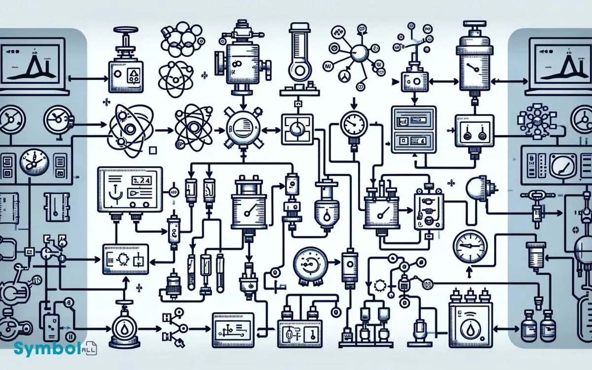
These symbols represent various instruments and their functions, from measuring to controlling process variables like pressure, temperature, and flow rate.
Understanding these symbols is essential for any chemical engineer, as they provide the means to convey intricate control strategies across multidisciplinary teams. Each symbol is standardized, ensuring consistency and clarity in communication.
For instance, a circle often represents an instrument accessible to an operator, while a square may indicate a computer function.
Recognizing these nuances allows you to not only grasp the operational aspects of a plant but also to contribute effectively to its design, optimization, and troubleshooting processes.
Separation Processes
In chemical engineering, separation processes are fundamental operations that allow you to isolate and purify specific components from a mixture based on their physical or chemical properties.
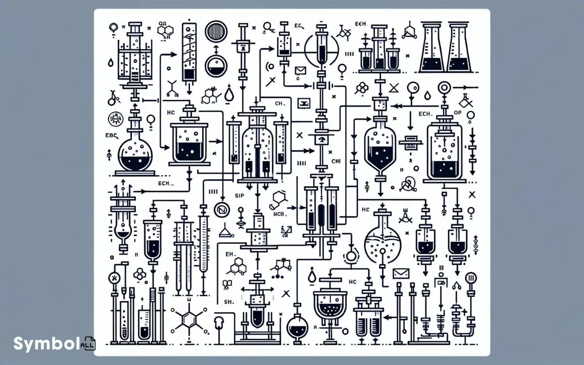
These processes are represented by distinct symbols in flow diagrams, each symbolizing a different method or apparatus.
For instance, distillation, a common separation technique, is depicted by a column symbol, indicating the separation of components via differences in boiling points. Similarly, filtration, which separates solids from fluids, is represented by a simple filter symbol.
Understanding these symbols is vital as they communicate the specific separation processes involved in a chemical engineering system, enabling you to analyze and interpret the flow of materials through various stages of separation.
This knowledge is essential for designing efficient separation units and optimizing existing processes.
Reactors and Mixers
Diving into reactors and mixers, you’ll find these symbols represent the heart of chemical processing, where substances are transformed and combined through controlled reactions and blending techniques.
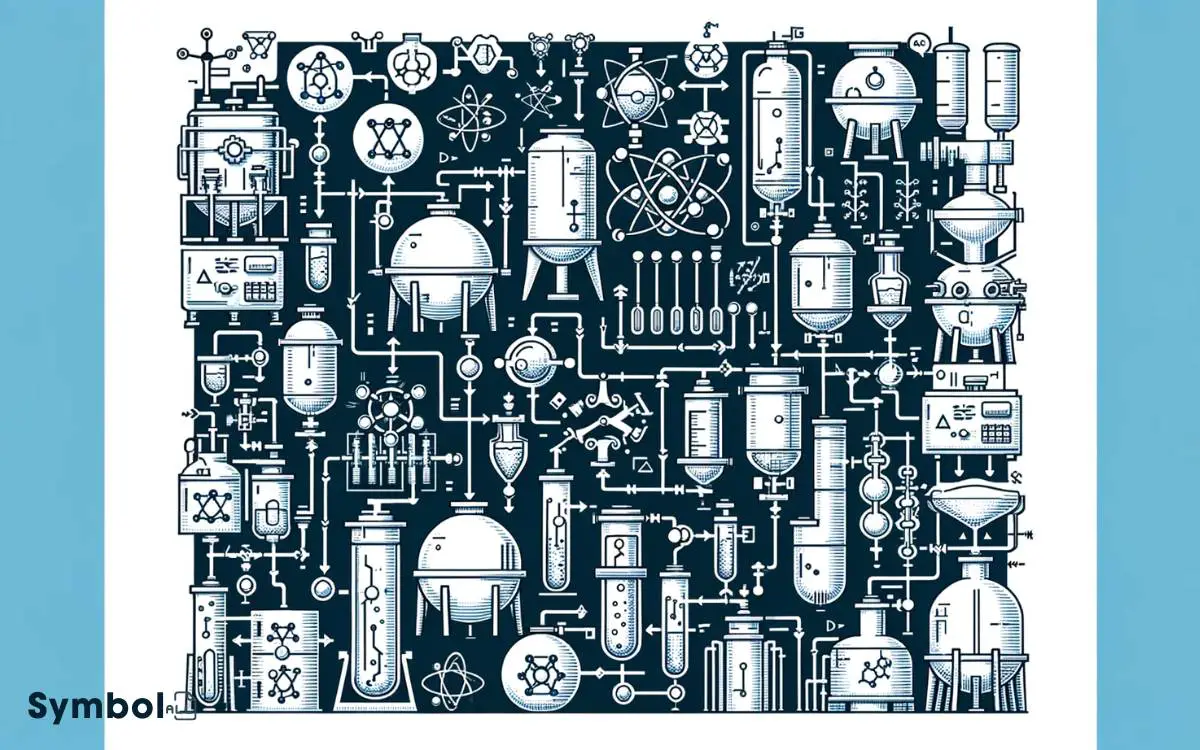
Reactors, depicted by symbols like the stirred tank or plug flow reactor, are critical for initiating chemical reactions under specific conditions of temperature and pressure.
Each symbol encapsulates a unique set of operational parameters and design considerations, essential for the accurate representation of the process flow.
Similarly, mixers, indicated by symbols such as the static or the mechanical mixer, play a pivotal role in ensuring homogeneous mixing of reactants.
Understanding these symbols allows you to grasp the intricacies of process design, ensuring efficient and safe chemical processing. The precision of these symbols in flow diagrams is crucial for the effective communication and realization of chemical engineering projects.
Safety Devices and Miscellany
Focusing on safety devices and miscellaneous items, it’s essential to grasp that these symbols indicate pivotal elements crafted to guarantee process operations are carried out securely and effectively.
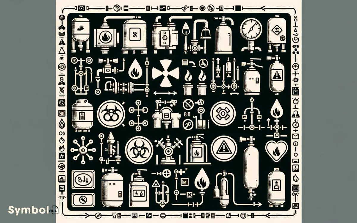
Understanding these symbols enables you to identify and implement safety measures within a chemical engineering process, ensuring both personnel and equipment are protected from potential hazards.
- Pressure Relief Valves (PRVs): These symbols represent devices designed to release excess pressure, preventing equipment failure or explosions.
- Flame Arresters: Indicated to stop flames from propagating through pipelines, thereby avoiding potential fire hazards in process flow.
- Detectors and Alarms: Symbols for devices that detect abnormal conditions (like gas leaks or overheating) and alert the operators, enabling timely intervention to mitigate risks.
Each symbol serves as a critical component in safeguarding the integrity of chemical processing environments, underscoring the importance of meticulous attention to safety details in engineering diagrams.
Conclusion
In wrapping up, it’s important to grasp the significance of these chemical engineering flow diagram symbols. They’re not just arbitrary markings; they represent the backbone of chemical engineering design.
Did you know that accurately interpreting these symbols can enhance the efficiency of a chemical plant by up to 30%? This statistic underscores the essential role that understanding and applying these symbols play in optimizing processes and ensuring safety.
Mastering them isn’t just academic it’s a practical necessity in the field.

